Hazardous voltage may be present.
Always isolate the electrical power supply before making or changing connections
to the unit. To remove the power it is recommended to use an isolating device.
Hazardous voltage is present until 60 sec after switch off. Do not handle the
controller during this time.
The controller housing must be properly grounded. Use the specified screws on
the feet of the controller housing.
Incorrect assembling of the “POWER INPUT” connector
➔
short circuit possible.
Assure that the correct
before it is plugged in.
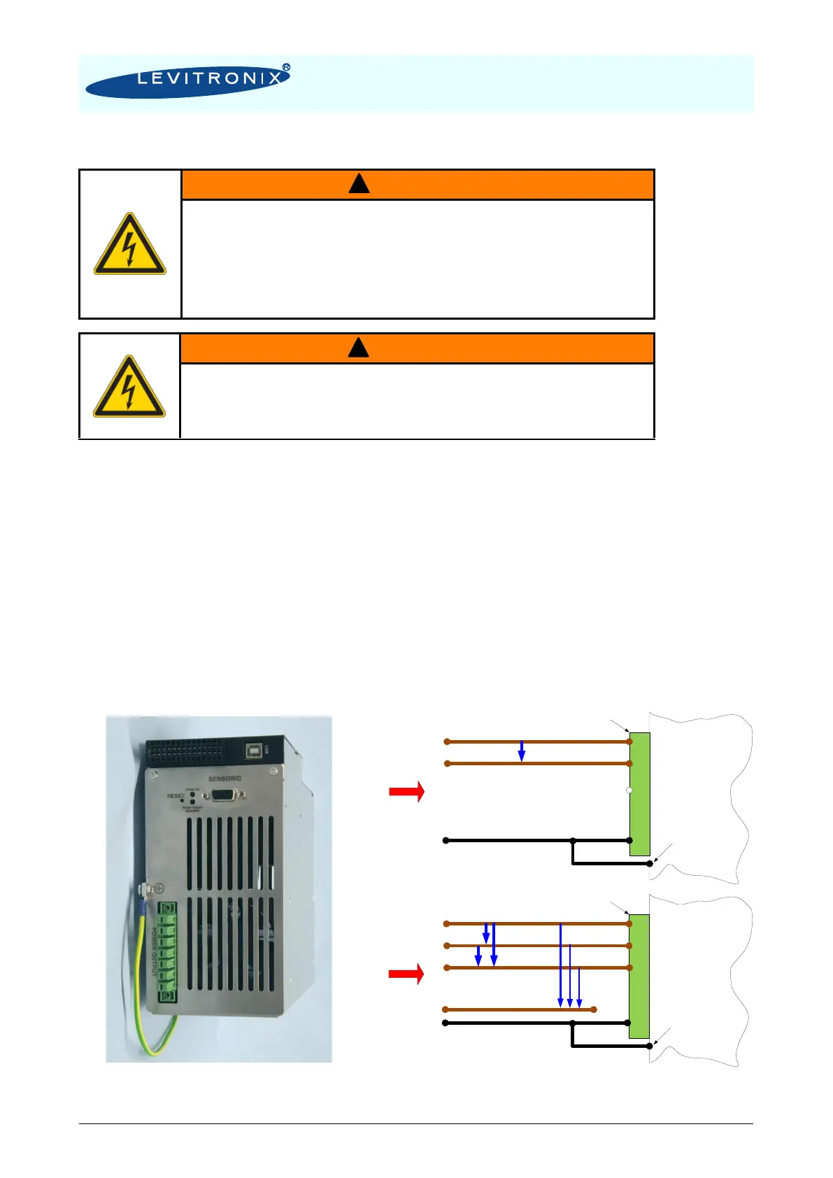
1. Connect the protective earth wire with a crimp-type end on the specified earth screw (see
Figure 27) on the feet of the controller (see also protective earth labels on controller).
2. Connect the two motor connectors (sensor and power) to the controller. Assure that the
“POWER OUTPUT” connector from the motor is correctly aligned with the connector of the
controller before it is plugged in.
3. Connect the AC power input connector. Make sure that the pin connections are correct:
- 1 x 200-240V (1-phase)
L1 (
L), L2 (
N), PE (= Protective Earth)
- 3 x 200-240V (3-phase delta voltage)
L1, L2, L3, PE (lines can be switched), star-voltage = 115 139 VAC
- Minimum Wire Gauge = AWG 14 (cooper diameter = 1.63 mm, cross section = 2.08 mm
2
)
- For usage of external circuit breakers consult Section 3.2.5.
4. To secure the connectors, tighten all retaining screws according to the torque specifications
in Table 12 (for LPC-2000.1) and Table 13 (for LPC-2000.2).