Repair information 4-7
2580+, 2581+, 2590+, 2591+
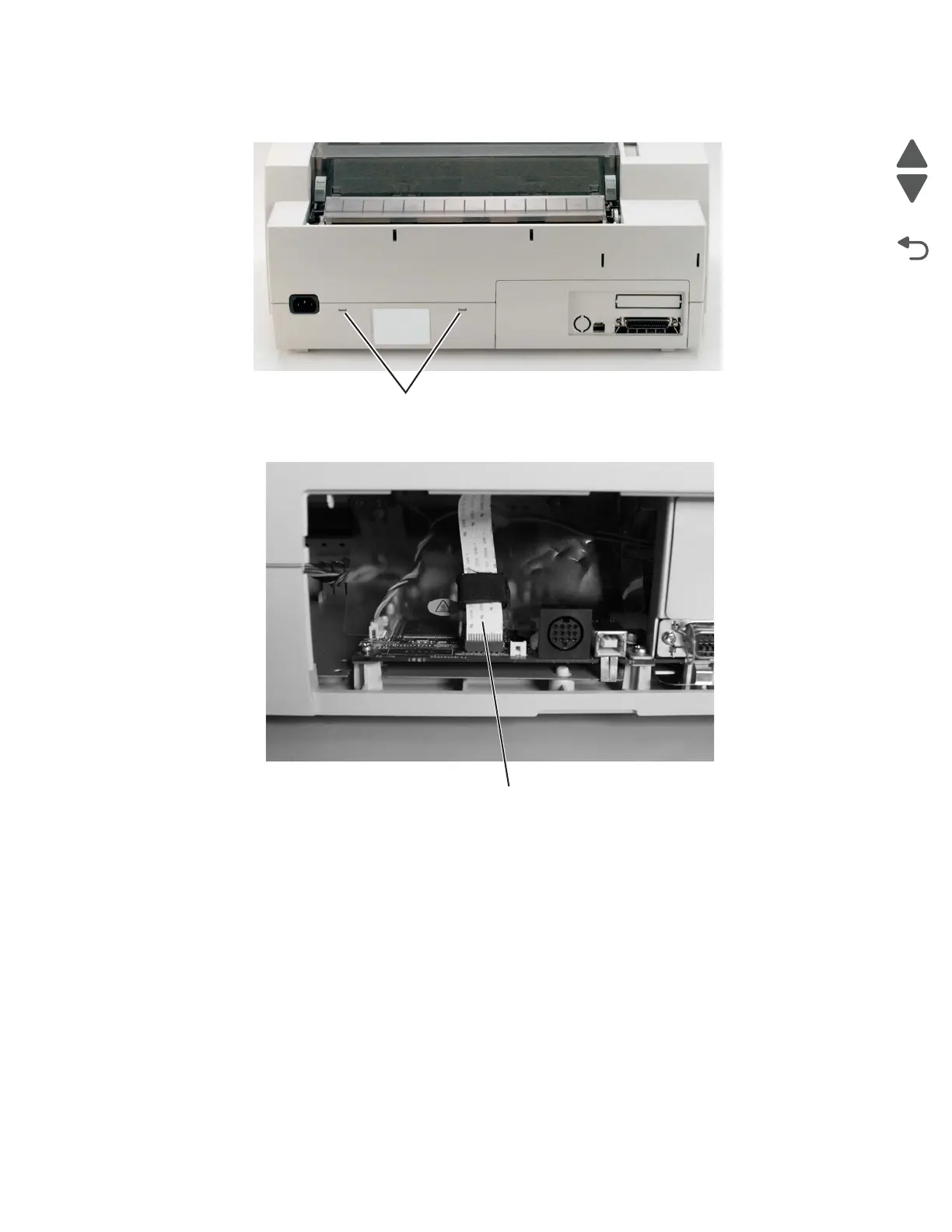
9. Turn the printer right side up, and insert a flat-blade screwdriver into each of the two holes (C) in the back
of the top cover.
10. Remove the rear cover. See “Covers, rear removal” on page 4-5.
11. Disconnect the operator panel cable (D) from the logic board.
12. Lift the top cover up and over the print unit assembly.
Note: When replacing the top cover, be sure the operator panel cable is correctly aligned and inserted securely
into the logic board. Damage to the operator panel cable may cause failure of other electrical components in the
printer.