4-8 Service Manual
2580+, 2581+, 2590+, 2591+
Electronics removals
INA support frame removal
1. Remove the rear cover. See “Covers, rear removal” on page 4-5.
2. Remove the top cover. Go to “Covers, top removal” on page 4-5.
3. Remove the network card. Go to “Network card removal” on page 4-9.
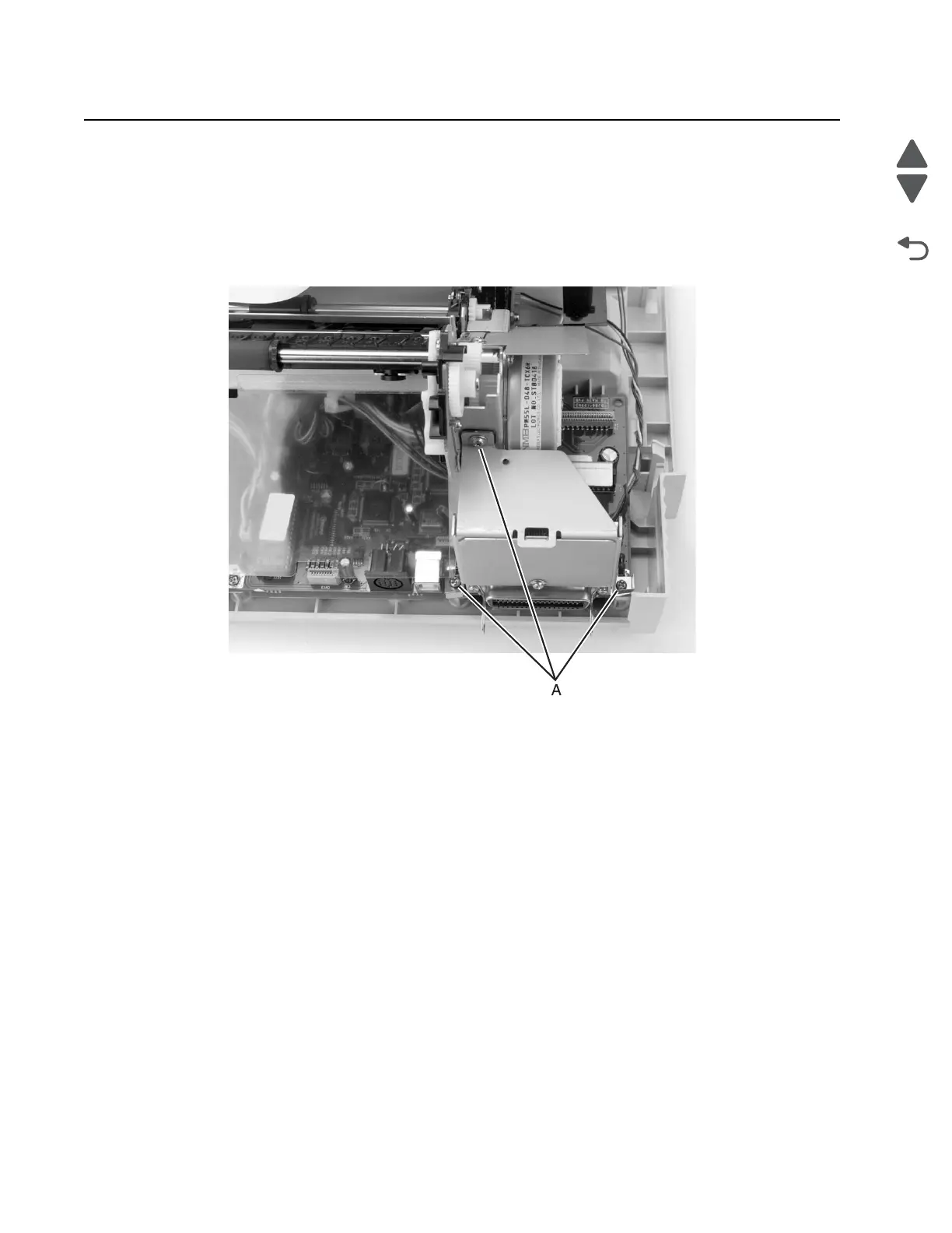
4. Remove the thre screws (A), then remove the INA support frame.
Note: To avoid printer alignment issues, make sure that the screw is not too tight when reinstalling the INA
support frame.
Logic board removal
1. Remove the rear cover. See “Covers, rear removal” on page 4-5.
2. Remove the top cover. See “Covers, top removal” on page 4-5.
3. Remove the INA support frame. See “INA support frame removal” on page 4-8.
4. Disconnect all cables connected to the logic board.
Note: Do not twist the flexible cable when disconnecting the printhead cable(s).