Lexmark T65x and X65x Mono Product Study Guide Rev 1.47
For Training Purposes Only 6/3/2009
15
Alignment assembly – skew adjustment
Do the alignment assembly adjustment whenever you replace the alignment assembly. Always print a
copy of the Quick Test Page before making any adjustments to the alignment assembly reference
adjustment screw. When replacing the alignment assembly, it is necessary to back the reference
adjustment screw out far enough to remove the old assembly and install the new one.
• If you are replacing the alignment assembly, go to step A.
• If you are only adjusting the reference adjustment screw, go to step B.
Step A
Print a copy of the Quick Test Page and check the margin adjustments printed on the test page. These
settings should be within the range specified in “REGISTRATION” shown below:
Variable Description Value Direction of change
T= Top margin -25 to +25 Each increment causes
approximately 4 pels shift (at 600
dpi).
A positive change moves the image
down the page and increases the
top margin. A negative change
moves the image up and decreases
the top margin.
B= Bottom margin -20 to +20 Each increment causes
approximately 0.55 mm shift in the
bottom margin.
A positive change compresses the
image so it appears to move down
the page and a negative change
moves the image up.
L= Left margin - -25 to +25 A positive change moves the image
to the right, and a negative change
moves the image to the left. No
compression occurs.
M= Right margin - 99 to +99 A positive change moves the image
to the right, and a negative change
moves the image to the left.
Do the reference adjustment if you are sure the margins are set correctly.
1. Loosen the locknut on the inside rear of the alignment assembly.
2. Remove the two screws holding the alignment assembly to the left side frame.
3. Back the reference adjustment screw out far enough to allow the alignment assembly to be removed
from the printer. It is not necessary to completely remove the screw.
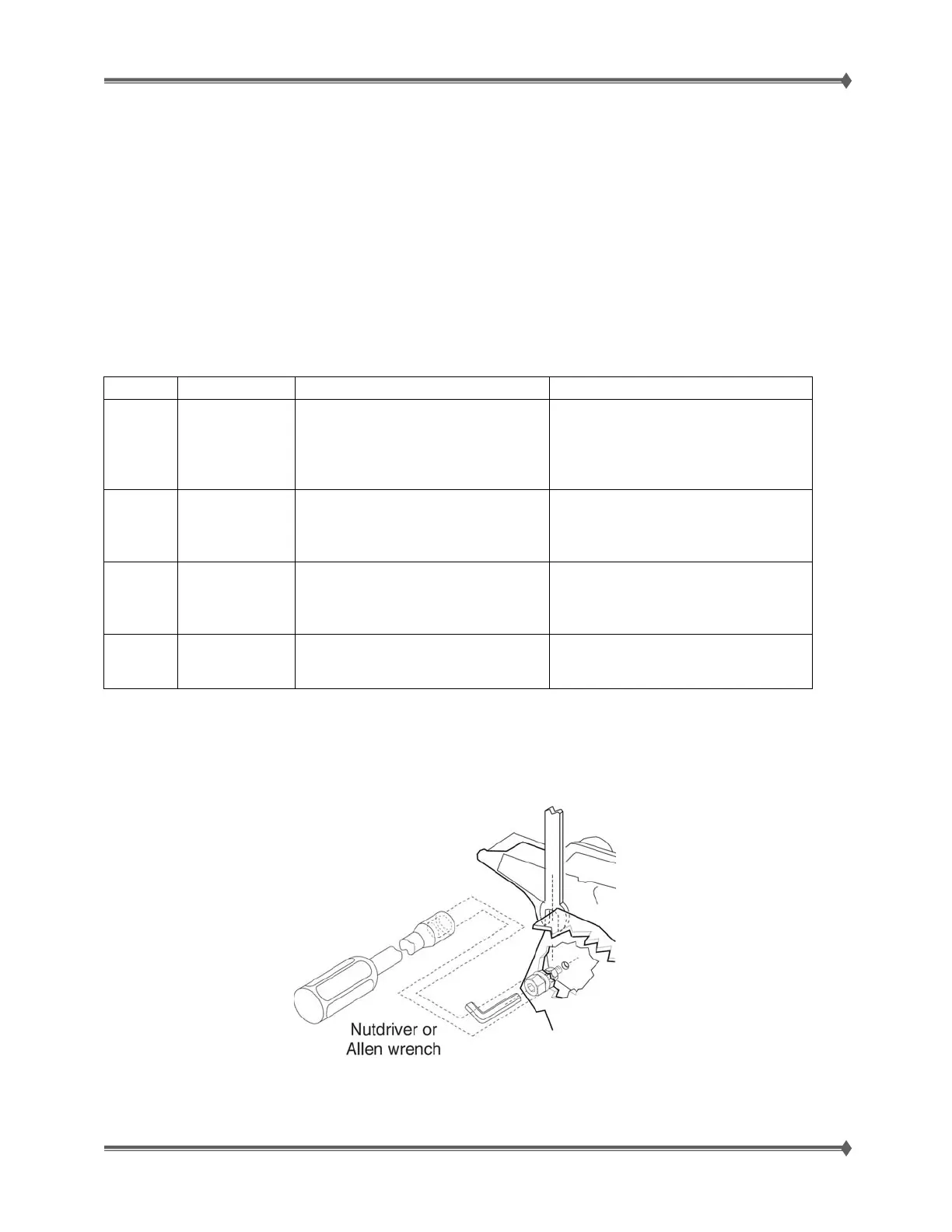
4. Install the new alignment assembly. Turn the reference screw clockwise with a 7 mm nut driver or M3
Allen wrench until it touches the back of the reference plate, and tighten the nut with a 5.5 mm
wrench.
 Loading...