300781172_002_C0 - 012/2019 - © Leybold 24
Installation
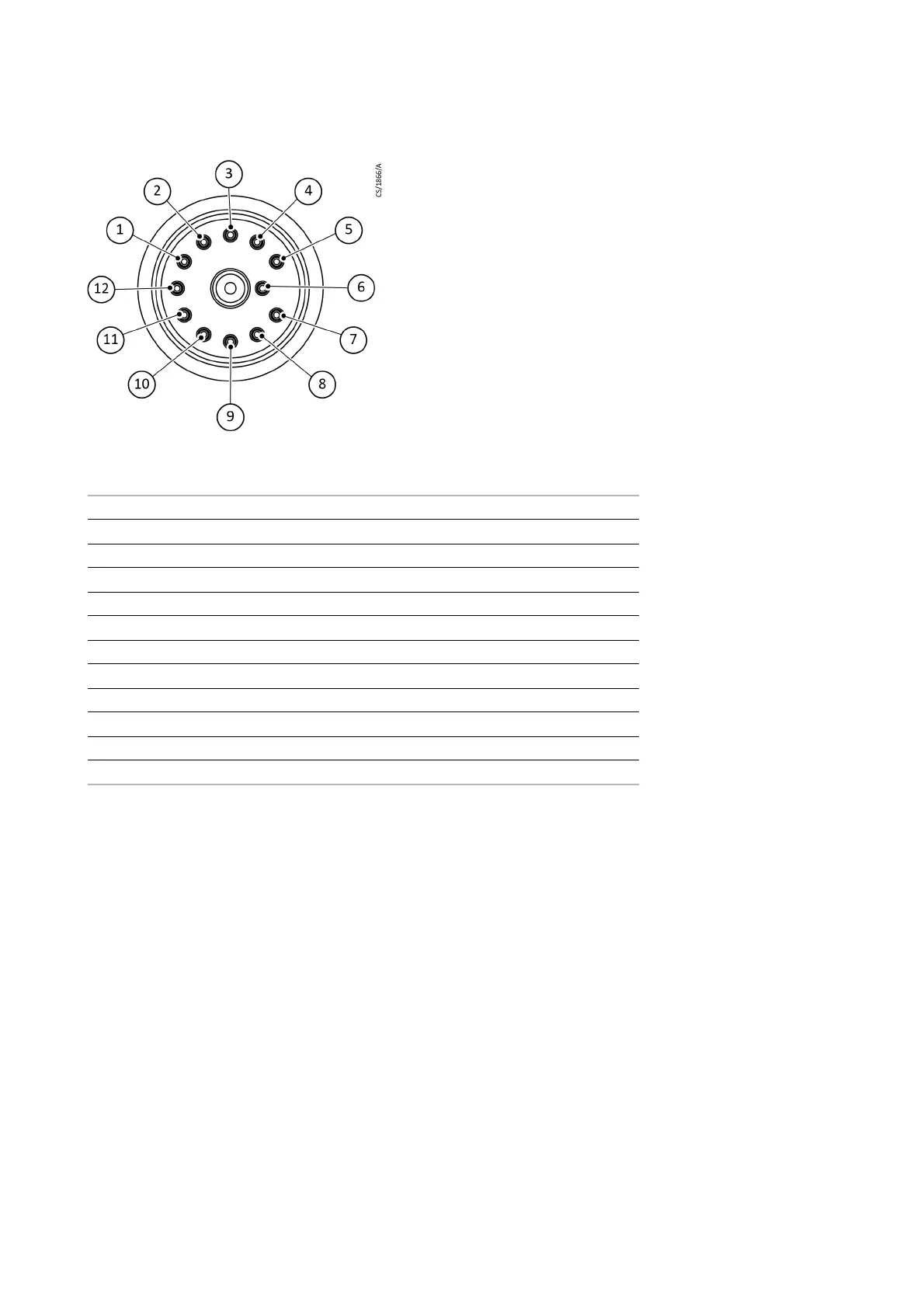
Fig. 4.2 Pin assignment as viewed from atmospheric side (LEYSPEC ultra )
3. Check for continuity and insulation
Check the insulation and continuity between each terminal of the analyzer tube and
between the terminals and earth.
Fig. 4.1 on page 23 shows the pin assignment of
the analyzer tube connector for LEYSPEC view models, and
Fig. 4.2 on page 24
shows the assignment for LEYSPEC ultra models.
For LEYSPEC view and LEYSPEC ultra models:
Check the insulation between terminals, except the HV terminal, and earth.
When the analyzer tube is equipped with a secondary electron multiplier (SEM), the
resistance between the HV terminal and earth is 19 M
Ω.
Check filament continuity from FIL1 to FIL.C and from FIL2 to FIL.C.
Measure the resistance. If the filaments are intact, the resistance is about 1
Ω. If the
filament is broken, the resistance is infinite (open circuit).
LEYSPEC ultra
1N.C.
2FIL.C
3RF2
4FOCUS
5N.C.
6HV
7FIL2
8FIL1
9TP
10 N.C.
11 GRID
12 RF1