15
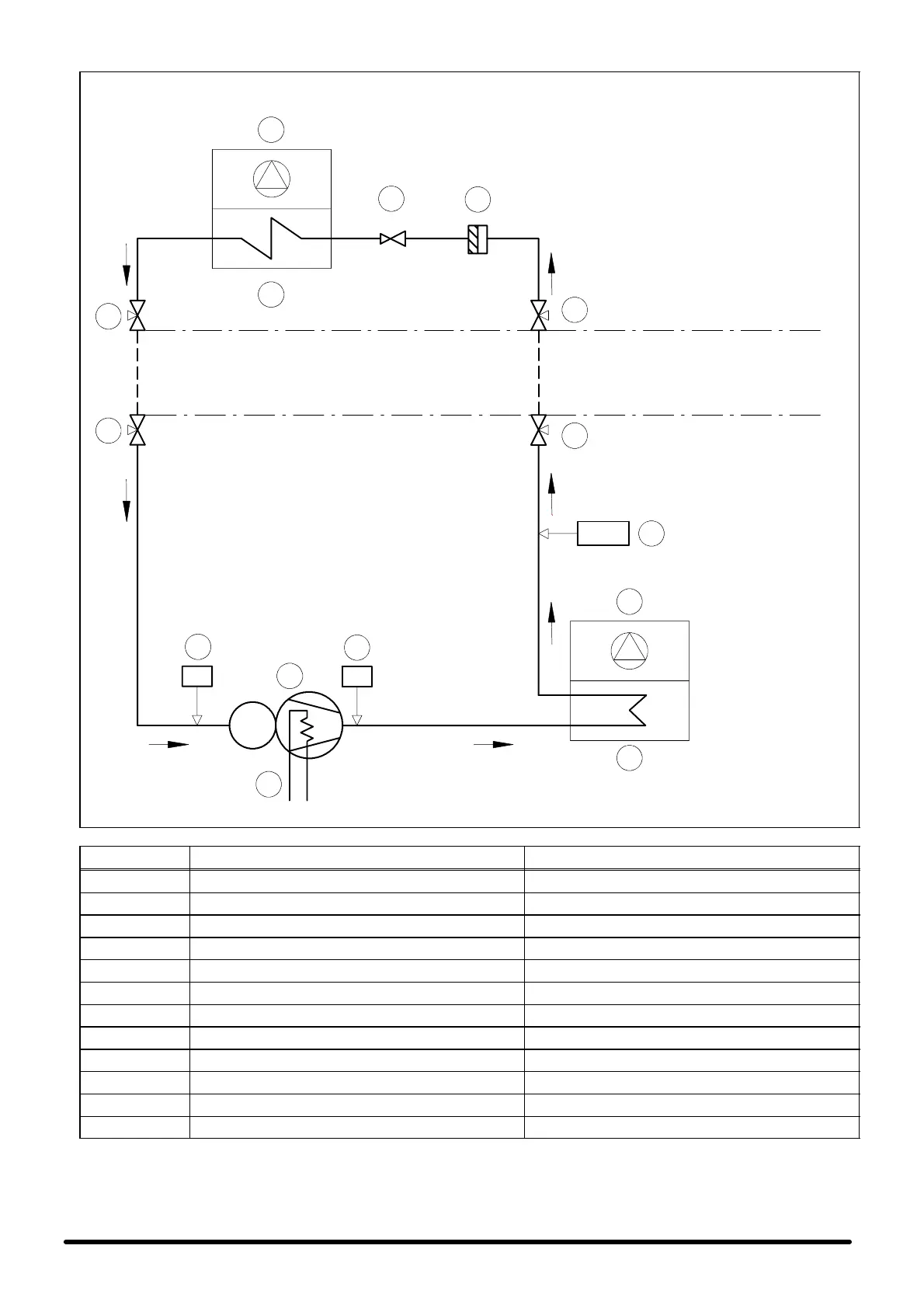
Fig. 11 --- Refrigeration circuit --- Schema frigorifero SE+SC 05---06
SE05+SC05 ø8
SE06+SC06 ø8
CONNECTION PIPING
TUBAZIONE DI COLLEGAMENTO
SE05+SC05 ø14
SE06+SC06 ø16
5
5
5
5
9
MC
6
10
11
EXTERNAL UNIT
UNITA’ ESTERNA
4
3
1
12
EV
LP HP
2
8
SUPPLY LIMIT --- LIMITE DI FORNITURA
SUPPLY LIMIT --- LIMITE DI FORNITURA
INTERNAL UNIT
UNIT A’ INTERNA
CONNECTION PIPING
TUBAZIONE DI COLLEGAMENTO
7
POS. DESCRIPTION DESCRIZIONE
1 Evaporator fan Ventilatore evaporatore
2 Evaporator Evaporatore
3 Expansion capillary Capillare d’espansione
4 Filter dryer Filtro deidratore
5 Shut---off valve Rubinetto di intercettazione
6 Compressor Compressore
7 Crankcase heating element Resistenza carter
8 Condenser fan Ventilatore condensatore
9 Air cooled condenser Condensatore ad aria
10 Low pressure switch Pressostato bassa pressione
11 High pressure switch Pressostato alta pressione
12 Fan pressure switch control adjuster Regolatore pressostatico del ventilatore