Do you have a question about the Lifetime 90135 and is the answer not in the manual?
Presents critical safety warnings and precautions for safe operation.
Connects the two front skids to the front cross brace using specified hardware.
Connects rear skids to rear and middle cross braces securely.
Joins the two main sub-assemblies created in earlier steps.
Places adjustment stands into the cross braces at the desired height settings.
Connects cockpit backrests to the seat back supports using the correct hardware.
Connects front fuselage parts to top and bottom fuselage sections.
Secures the assembled fuselage frame using hardware and T-nuts.
Places the back seat support between the fuselage frames and secures it.
Attaches the front seat support between the fuselage frames securely.
Positions the cockpit seat support and finger-tightens the hardware.
Places the cockpit seat onto the fuselage and secures it with hardware.
Lifts the fuselage assembly onto the base assembly and aligns holes for connection.
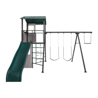
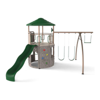
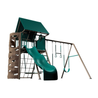
| Model Number | 90135 |
|---|---|
| Assembly Required | Yes |
| Material | High-Density Polyethylene (HDPE) and Steel |
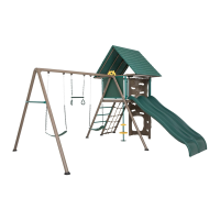
| Color | Green |
| Age Range | 3-12 years |
| Included Components | Slide, Swing Set, Climbing Wall |
| Warranty | 5-year limited warranty |