THE BLUE BOX LT GR1404/08 LT INSTALLATION GUIDE 115
LCDBB1404/08IG03Sept08
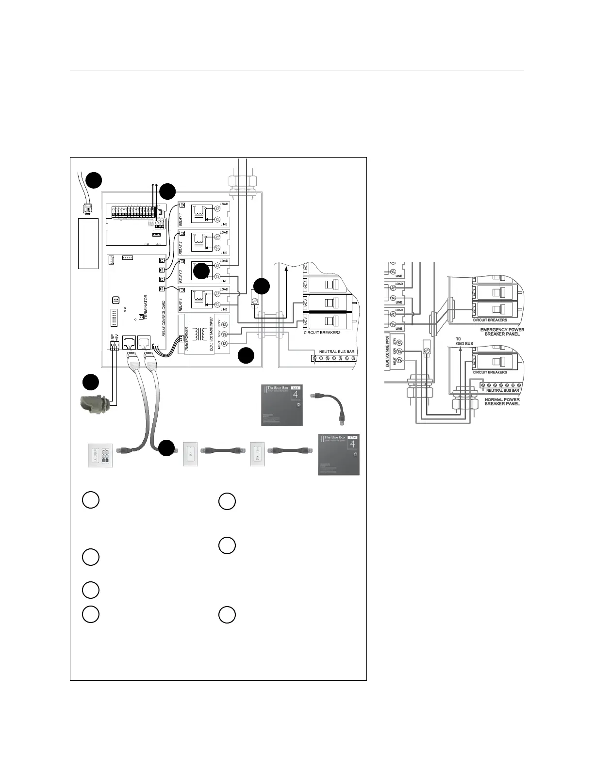
HOOk UP DIAGRAMS
EMERGENCY LOADS
To switch relays on in the event of a
loss of normal power, feed the power
supply with a dedicated normal-pow-
er breaker.
To maintain relay status (on or off) in
the event of a loss of normal power,
feed the power supply with a dedi-
cated emergency-power breaker via
a server-quality UPS (load is less than
10 watts).
Relay lugs may hold up to 1.
4#10 or 2 #8 AWG. Neu-
trals may be run through
Blue Box gutter.
Power supply lugs may hold 2.
up to 2#12.
Equipment Ground Lug.3.
2#18 AWG from photocell 4.
input (master panel only) to
outdoor photocell (up to
300 ft).
Daisy-chain switches and 5.
panels using Cat. 5 cable
with RJ45s.
Wiring details from contact 6.
closure switches to (optional)
Digital Input (DI) Card are
shown in the “DI Installation
Guide.”
Run phone cable from mo-7.
dem to an analog phone jack.
See back for details.
1
4
5
3
2
6
7
1
4
5
6
3
2
Chelsea Digital Switch
Outdoor
Photocell
7
Master Blue Box (DTC not shown)
2#18AWG - 4#18AWG
for each contact-closure switch
Slave Blue Box
 Loading...