42 THE BLUE BOX LT ADDING A NEW DEVICE
LCDBBAND04Sept08
HARDWARE ACTIvATION TESTS
Before starting, note total approximate bus cable length:
Once each cable has been checked with a LAN cable
tester and plugged-in, it is still possible for the entire con-
nected cable structure to be problematic. For instance,
dirt may have accumulated inside the RJ45 sockets, the
strain on the Cat. 5 when pushing switches into the wall
may weaken connections or even break the conductors,
or the bus length may exceed 4000 ft.
Each test must be passed before moving onto the next. If
any readings are out of range, refer to “Hardware Activa-
tion Troubleshooting” section at the end of this document
or call Technical Support at 1-800-345-4448.
CONTINUITY TEST
This test is intended to verify bus length, continuity, and
detect crossed data-pair wires.
1. De-power every item on the bus and check the voltage
at both ends to ensure a reading of 0vdc. Remove any
terminators.
2. At one end of the bus, plug in the “Data/Power Jumper.”
3. At the other end of the bus, plug in the “Bus Checker Card”
and measure resistance across the following terminals:
Gnd to A ____ohms B to +12 ____ohms
4. All test values must be within 10% of the values in the
chart below to be considered valid!
Length Ohms Length Ohms
100 ft 3 Ω to 6 Ω 2000 ft 68 Ω to 80 Ω
500 ft 12 Ω to 20 Ω 3000 ft 102 Ω to 120 Ω
1000 ft 34 Ω to 40 Ω 4000 ft 130 Ω to 160 Ω
Continuity Test Results (Gnd to A & B to +12)
SHORT CIRCUIT TEST
This test is intended to detect any short circuits along the
bus. Please use the lowest resistance range (200 Ω) setting
on your multimeter. DO NOT use a “beep” test.
5. Remove the “Data Power Jumper.” On the “Bus Checker
Card,” measure the resistance across the following terminals:
6. All test values should be greater than 1K ohm!
Gnd to A ____ohms A to B ____ohms
Gnd to B ____ohms A to +12 ____ohms
Gnd to +12 ____ohms B to +12 ____ohms
EARTH GROUND TEST
This test is intended to detect any pathways to earth
ground.
7. Measure resistance between the terminals mentioned be-
low, and “Earth ground” (a metallic enclosure or conduit).
Gnd A
+12 B
8. All readings between each terminal and “Earth ground”
should be infinite or “Open”!
TERMINATOR TEST
This test is intended to ensure that only 2 terminators
exist, one at each end of the bus. If the readings are out of
range, it would indicate a missing, misplaced, or an extra
terminator.
9. Add a “Terminator” on the first and last device. On the
“Bus Checker Card“, measure
A to B ____ohms
10. Test reading should be within 62
Ω to 92 Ω!
11. Remove the bus checker card and call our Tech Sup-
port with your results at: 1-800-345-4448 x391.
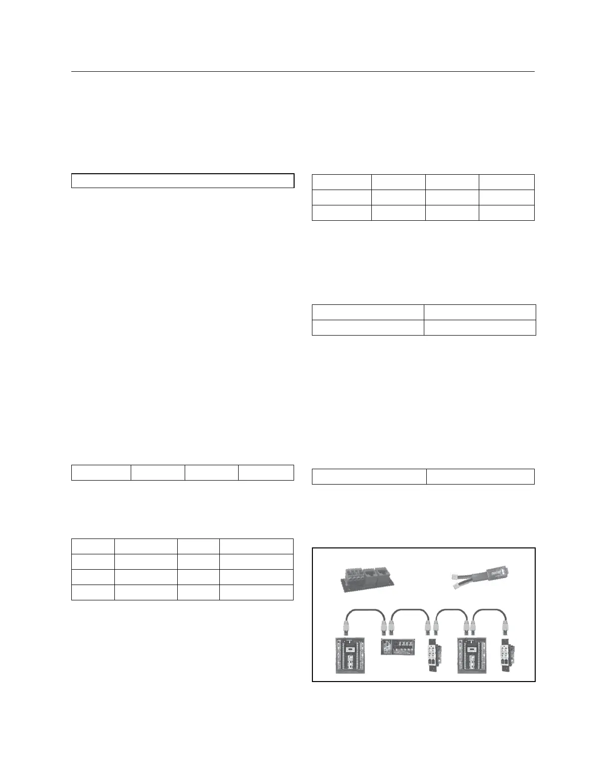
Bus Checker Card
Figure A:
Data/Power Jumper
 Loading...