LCDBBPRIG03Sept08
52 THE BLUE BOX LT PARTS REPLACEMENT & INSTALLATION GUIDE
Item Bus Map Name
DI-6 14 Btn. Switch
Any Digital Switch that is
enabled or disabled
14 Btn. Switch
Re-program schedules and groups
Since the master panel control card is also 15.
the system clock, all programs will need to be
programmed back into the clock.
Any groups which had relays in LCP 1 will need 16.
to be modified to add back the relays from LCP 1.
Relays from other LCPs will automatically appear
on the Groups screens.
CONTROL CARD [SLAvE] REPLACEMENT AND
INSTALLATION
To remove a defective Control Card
Note the address of the LCP (lighting control 1.
panel). Refer to the SYSTEM DEVICE SCHEDULE
in the Master Panel or use the READ ADDRESS
screen.
De-power the Blue Box LT by switching off the 2.
breaker feeding the power supply (the relays in
that panel will close).
Once the panel is de-powered, disconnect all 3.
cables connected to the control card.
Pry the Control Card out of the plastic track by 4.
applying a flat-blade screw driver to the slot on
the side of the card. [Note: If this is a warranty
replacement, do not forget to ship relay back to
LC&D.]
To replace a defective Control Card
Snap the new control card into the plastic track.5.
Re-connect all cables and conductors to the 6.
Control Card.
Re-power the Blue Box LT.7.
After the defective part replacement installation 8.
is complete, return the part using the prepaid
USP return label and envelope to LC&D.
[Note: If the defective part is not returned within a
30-day period, your account will be automatically billed
for the part. ]
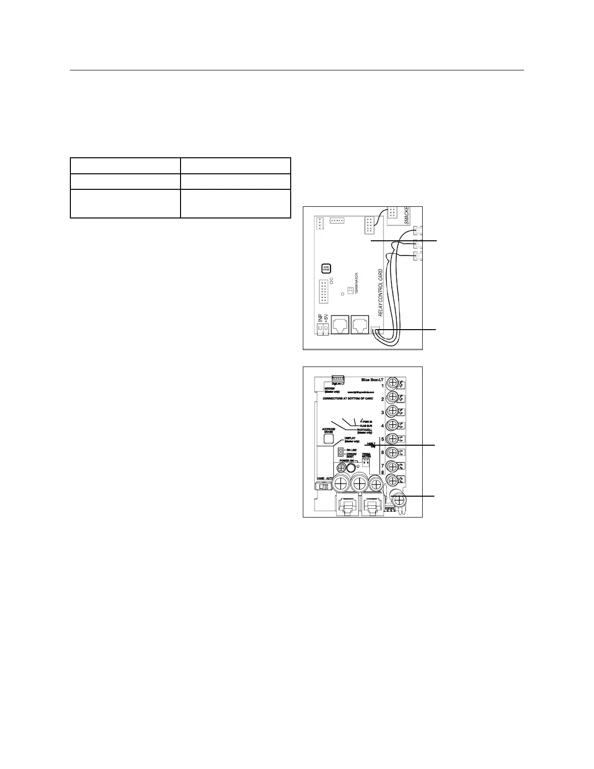
Slave Control Card
Power
Slave Control Card
Power
To address and verify the bus recognizes replace-
ment Control Card
Navigate to the AUTO ADDRESS screen: 9.
USER MENU> SET UP MENU> RESTRICTED
(PASSCODE: 900001) > ADDRESSING BUS
SCAN > AUTO ADDRESSING.
SCROLL UP until the address of the LCP is 10.
displayed.
Press the address button on the Control Card. 11.
If the address “takes” the address on the display 12.
will increase by one for an LT4 and LT-8, or 2 for
an LT-16) (e.g. from “3” to “4”).
 Loading...