LCDBBPRIG03Sept08
THE BLUE BOX LT PARTS REPLACEMENT & INSTALLATION GUIDE 55
TRANSFORMER REPLACEMENT AND
INSTALLATION
To remove a defective Transformer
De-power the Blue Box LT by switching off the 1.
breaker feeding the power supply (the relays
in that panel will close). De-power any other
breakers that may present a hazard during
installation.
For master panels: Unscrew and open the hinged 2.
display-panel door to expose the high-voltage
section.
Remove the screw and lockwasher fasteners 3.
that hold the line/low voltage barrier on top of
the power supply (transformer) and remove the
barrier to free it up.
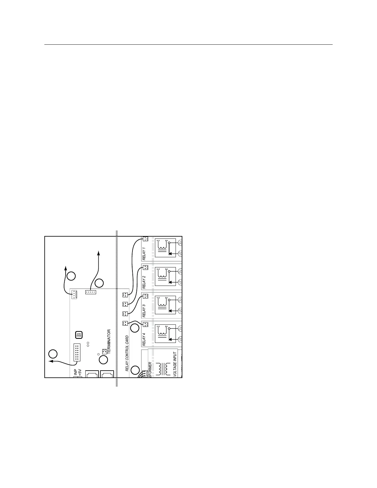
To DTC
To optional Modem
master panels only
To optional DI Card
3#18 AWG. Supplies power and neutral from transformer
to relay control card.
14 Conductor ribbon cable: carries control signal
between DTC and relay control card (master panel only).
2 conductor ribbon cable: carries control signal from
relay control card to relays - onbe per relay.
_____ cable: carries digital siganl from relay control card
to (optional) digital input card
_____ cable carries rs-232 signal from (optional) modem
to relay control card (master panel only)
Terminator / terminator pin-outs. (provided inside master
panel) - terminaties bus line.
3
4
5
6
1
2
3
4
5
6
1
2
Low Voltage High Voltage
Low Voltage/High Voltage Barrier
Loosen the hot and neutral connection lugs on the trans-4.
former’s terminal block and remove the conductors.
Pull off the low voltage connector(s) (one wire 5.
for LT 4 and 8 and three wires for LT 16) that
connects the transformer to the control card.
For LT 4 and 8: Pry the transformer out of the 6.
plastic track by applying a flat-blade screw driver
to the slot located at the card’s edge near the
hot and neutral lugs. For LT 16: Remove the four
screws at the base of the transformer.
To replace a defective Transformer
For LT 4 and 8: Push the new replacement 7.
transformer into the track until it “snaps” securely
in place. You may need to use a flat-blade
screw driver to snap in one or both ends. For
LT 16: Mount the new transformer with the four
screws.
Reconnect the low voltage connectors.8.
Reconnect hot and neutral conductors9.
Re-install the line/low voltage barrier and the 10.
screw and lockwasher fasteners.
For master panels: Close and screw down the 11.
hinged display -panel door.
Re-power any breakers.12.
After the defective part replacement installation 13.
is complete, return the part using the prepaid
USP return label and envelope to LC&D.
[Note: If the defective part is not returned within a
30-day period, your account will be automatically billed
for the part. ]
To exercise the replacement Transformer
Visually inspect that the ONLINE LED on the 14.
control card is blinking and the clock is powered
up and displaying correctly.
Navigate on the DTC to USER MENU > 15.
MANUAL OVERRIDE and TAB or SCROLL to
the correct LCP and Load (relay). Exercise each
relay by manually switching it on and off 3 or 4
times. If possible, listen to hear the relay contacts
clicking as they open and close.
 Loading...