LCDBBPRIG03Sept08
56 THE BLUE BOX LT PARTS REPLACEMENT & INSTALLATION GUIDE
1
2
3
2
4
10
5
6
7
8
9
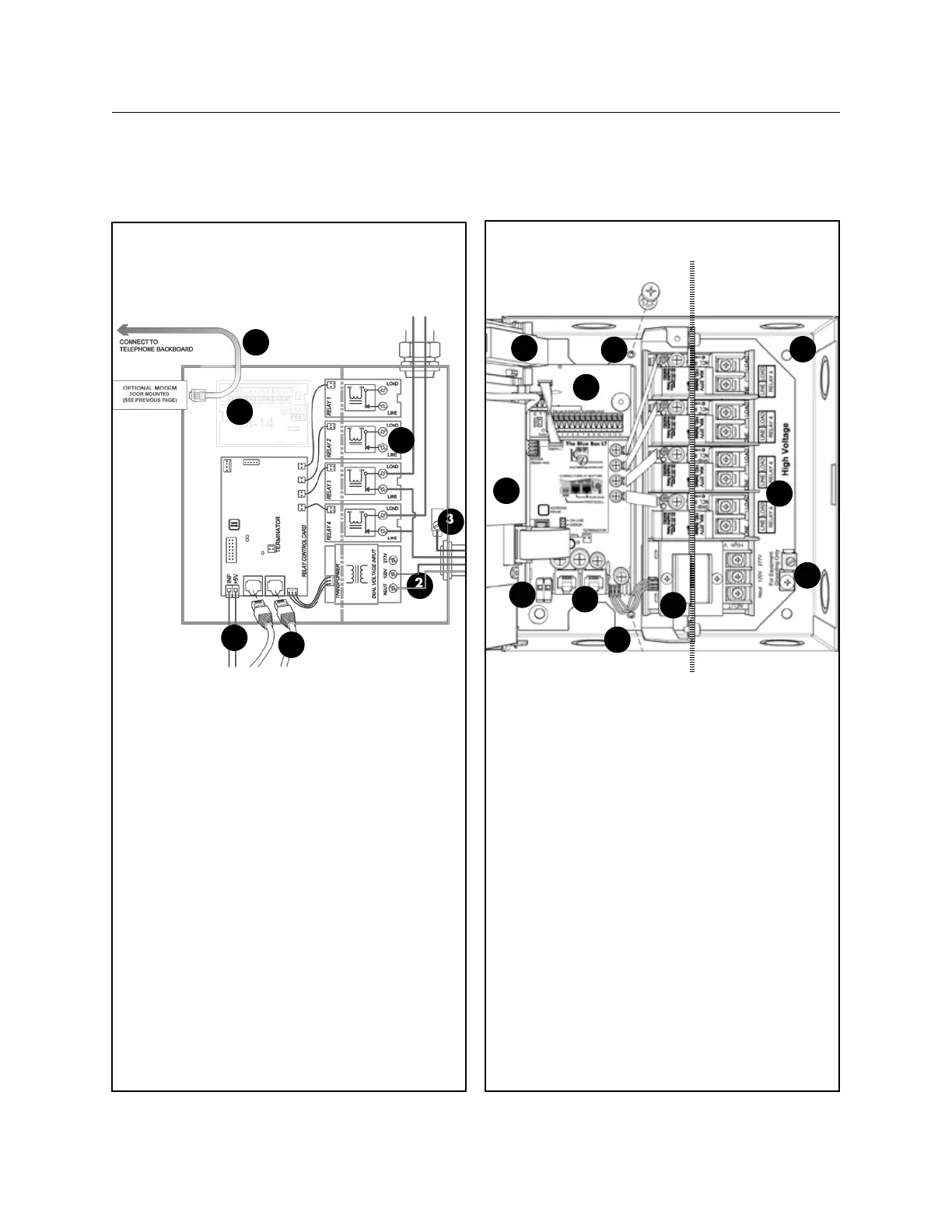
low voltage only line voltage only
Blue Box mounting holes (4).1.
Back plate mounting screws.2.
RJ45 sockets for GR 2400 bus.3.
Photocell input (master only). The Pho-4.
tocell may control any relay(s) in any
panel(s).
Optional modem. Analog phone line con-
5.
nects to RJ-12 socket.
Relays (line and load lugs).
6.
Dual-voltage (120V or 277V)power 7.
supply.
(Optional) Digital Input Card. [DI] 14
8.
(or 6 enable/disable) inputs.
Terminator pins. Terminate the bus only
9.
after the “System Start-Up and Cabling
Guide” has been completed.
Clock backplate and back of DTC clock
10.
(for the master panel only).
3
2
3#18 AWG. Supplies power and neu-1.
tral from transformer to relay control
card.
1-14 conductor ribbon cable: carries
2.
control signal between DTC and relay
control card (master panel only).
4(1404LT)/ 8 (1408) 2 conductor rib-
3.
bon cable: carries control signal from
smacker strip to relays - one per relay.
Terminator / terminator pin-outs. (pro-
4.
vided inside master panel) - terminates
bus line.
1
4
5
6
7
BLUE BOX LT 1404/1408
 Loading...