testing two independent mono communication channels. Set LA102 configuration Y1 to
automatically store sequence results and press
. A sequence can now
be sent to the LA102 L channel input by running a sequence with the L channel selected
on the LA101 (press
on the LA101 when in sequence mode to set the LA102
measurement channel). Another sequence can now be sent with the R channel selected
and this will leave the results for the first mono channel in memory 1 and the results for
the second mono channel in memory 2.
3.12 Single Register Operation Single register operation Comparing two mono tests
Each results memory has two registers, numbered 1 and 2, which are are normally used to
hold the left and right channel results respectively. However, it is often convenient to
compare the results of two separate mono test runs on a single printout or display, and this
can be done using ‘single register’ operation to use the two results ‘registers’ separately.
Each register will then hold results for a single channel (and either register can hold L or
R channel results).
To run two mono sequences and store the results in the two registers for comparison, first
clear the LA102 results memory by pressing
and then press on
the LA102. The display will show
SEQ and REG?. Press on the LA102 to select
register 1 and run a single channel sequence test by pressing
on the LA101.
The results will be stored in register 1. Now repeat the operation but press
to make the
LA102 use register 2.
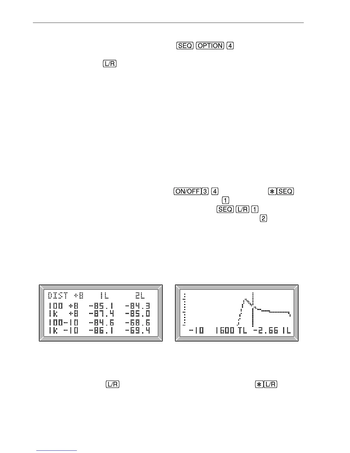
The results will be displayed and printed as for normal stereo results, but the column
headings will show the register numbers ‘1’ and ‘2’ in addition to the channel letter (L or
R). Note that it is quite permissible to have two sets of L channel results, one in each
register, as shown in fig. 3.17.
Fig. 3.17 Results for Two Registers Fig. 3.18 Register 1, L Channel
Frequency response graphs also indicate both the register number and the channel letter
(see fig. 3.15). Use the
key to switch between the two graphs and to show
the difference between the two responses (register 2 minus register 1) This can be useful
when comparing a frequency response in register 2 against a reference response in
52
3. Sequence Testing