corrects the output to give the displayed power in dB(1mW), indicated by dBm, into a
600
load for any selected output impedance.
Note that 10
output impedance should always be selected on the LA101 when the rear
XLR sockets are being used, and that 75
or 600 should be selected when the front jack
sockets are being used.
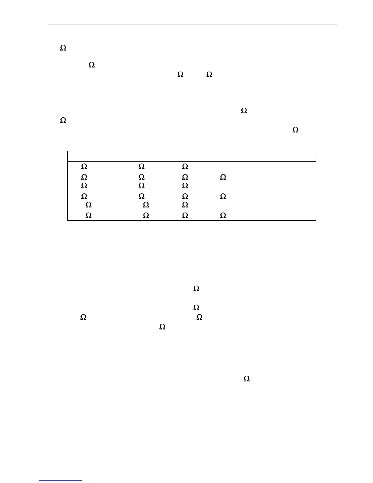
Table 2.19 summarises the different settings available, for various source and load
impedances. Note that it is quite acceptable to feed a 600
load from the LA101 with
600
output impedance and no ZC providing it is understood that the displayed output
level refers to the unloaded open circuit output level. Connecting the 600
output will
cause a 6.02dB drop which the LA101 will correct if the ZC mode is selected.
Display Front jacks Rear XLRs Load Z Output correction
10 75 10 high 0.00dB
10 ZC 75
*
10 600 +6.02dB
75 75 10 high 0.00dB
75 ZC 75 10
*
600 +1.02dB
600 600 10 high 0.00dB
600 ZC 600 10
*
600 +6.02dB
* Note that it is meaningless to use these conditions, because the LA101 is trying to correct for a different
source impedance to that being used.
Table 2.19 Impedance Correction Modes
It is important that this feature is used correctly. When ZC is selected the displayed
power level is only meaningful when a 600
load impedance is connected. Using the
wrong sockets for the selected impedance may be confusing; for example, the output from
the XLRs will increase by around 6dB if 600
ZC is selected, though the impedance will
still be 10
. Using the jack sockets in the 10 setting for equipment tests is permissible
though: the impedance will be 75
, but the lack of Z-correction ensures correct output
level provided a high impedance input is being fed.
2.22 dBu, dBV, Volts and Power Measurement Volts
The LA101 normally displays the absolute level being generated in dB relative to 0.775V,
or dB(0.775V), indicated by the symbol dBu. When a 600
load is connected and ZC
turned on, the displayed units change to dBm to show that the level is the power into the
load. However, configuration U allows other units to be used (U0 being the default).
Setting U1 causes the LA101 to work in dBV units where 0dBV is 1V, or +2.21dBu.
Setting U2 displays dBu and Volts (see fig 2.20), while setting U3 displays dBV and
Volts (note that the up/down keys still change the level in 1 or 0.01dB steps, they cannot
be made to change the level in voltage steps). The voltage displayed represents the
31
2. Manual Operation
 Loading...