SMARTNEO OPERATING MANUAL // PAGE 16
NOTICE LOGICDATA recommends using the drilling template on page 13 to mark the positions
of the Mounting Screws. If you choose not to do so, pay close attention to the dimensi-
ons of the SMARTneo-2G / SMARTneo-3G.
1. Position the SMARTneo-2G / SMARTneo-3G under the table top and mark the position of the
drilling holes. If necessary, use the Drilling Template on page 13 to help you.
2. Drill the holes into the table top.
3. Use the screwdriver and 2 Mounting Screws to attach the SMARTneo-2G / SMARTneo-3G to
the Table Top at the drilled holes.
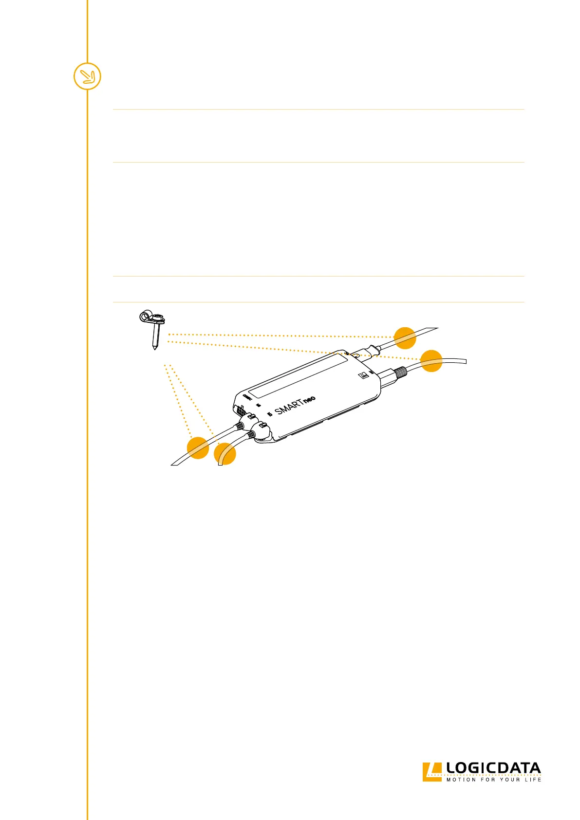
4. Attach Cable Clamps roughly 10 cm from any Plug Port that will be used (Fig.5).
NOTICE Required tightening torque depends on the material of the Table Top. Do not exceed 2 Nm.
Example Clamp
Fig. 5: Positioning the Cable Clamps
5.4 COMPLETING ASSEMBLY
After the SMARTneo-2G / SMARTneo-3G is attached to the Table Top, you must connect the Control Box to
the system. Instructions for this can be found in the next chapter.