10
Machine Description
PH 260 is a panel planer/moulder that processes the work piece
on four sides.
The machine is enclosed in a sturdy frame made of 4 mm (0.15”)
sheet steel. The machine table and the carriage for the moveable
side cutter are made of cast iron.
Supported by the machine table, the work piece is fed through
the machine by three feed rollers and one out-feed roller. These
feed rollers are run via a chain transmission with a separate
motor. The work piece is laterally guided by adjustable fences
and pressure rollers.
The machining of the wood is made by an upper cutter and a
lower cutter that are suspended at both ends, and two side cut-
ters that are tted in the machine table. All the cutters are run
by separate motors via belt transmission.
The cutters and the feed rollers are covered by a raisable pro-
tective cover with clear plastic windows. The protective cover
is equipped with a safety switch. An additional safety switch is
placed behind the upper edge of the safety ap on the in-feed
side. Each of the cutter heads has a 100 mm (4”) duct for chip
extraction.
Setting up the PH 260
Inspect your PH 260 immediately on reception. Any transport
damage must be notied immediately to the freight company.
As most of the machine’s structure is protected against rust, it
can stand in unheated storage spaces. However, extra main-
tenance is then required in the form of lubrication of parts that
are not rust protected (see Maintenance).
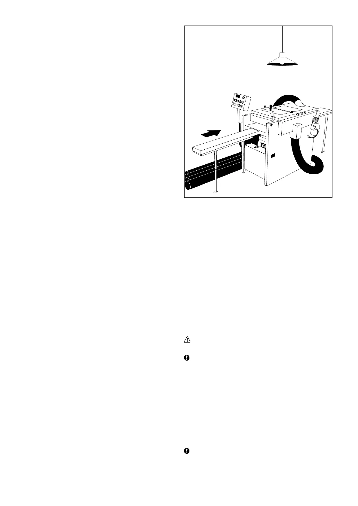
- Place PH 260 on a rm and level oor. If a castor set is not
used, the machine should preferably be screwed to the oor
through the holes in the bottom of the chassis.
- Make sure that there is free room on the in- and out-feed
side for the longest boards that are to be planed, and that
there is space provided for servicing and board stacks.
- Connect the four chip hoses, and fasten them with hose
clamps both on the planer end and the chip extractor end.
- Fix the machine’s power cable to the ceiling or protect it in
some other way. Never tread on the cable. The machine
should be connected via a residual circuit breaker.
- Ensure the lighting is rst-class. You should have good main
lighting, and also have a powerful lamp above the machine.
Ensure that there is no risk of being dazzled by the light.
Planer Shavings Collection
PH 260 must be connected to a chip extractor with a capacity
of at least 2500 m
3
/h. Logosol has a suitable 400 V, 3-phase
chip extractor of 3 kW with a no-load ux of 4000 m
3
/h (ref. no.
7000-000-2030). This extractor has four inlets with a diameter
of 100 mm (4”), and an outlet of 200 mm (8”). The chip extractor
has no chip collection bag, since such a bag should get full too
quickly. Instead you should build a chip pocket, or blow the
wood debris directly into a trailer or the like. Bear in mind that
there has to be an air outlet in your chip container (e.g. a ne-
meshed net, or a lter if you collect the wood debris indoors).
Poor extraction capacity is often due to a too limited air ow out
of the chip container. If you keep the machine in a heated room,
the chip extractor will soon cool the room if you do not direct the
air back into the facility.
Dust emission and risk of re have to be taken into consideration
when collecting wood debris.
Risk of re and dust emission when collecting wood
debris.
Consult your local authority about the regulations in your
district.
- Connect the chip hoses, and fasten them with hose
clamps both at the planer end and the chip extractor end.
Use the Flexi Hose from Logosol (length: 3 m, ref. no.
7000-000-1015), which has a smooth inside improving the
ow.
- If you want to convey the wood debris a long way, you should
place the chip extractor close to the planer so that you can
use as short hoses as possible. Convey the wood debris
in a sheet metal pipe, which reduces resistance for the air
ow.
Place the chip extractor so that its power switch is easily
accessible.