12
Control Panel
The control panel is not mounted when you receive the machine,
but lies inside the machine on the machine table. The control
panel is to be mounted on the in-feed side of the machine. In
the parts box, which also lies on the machine table, there are
two bolts that should be used for mounting the panel.
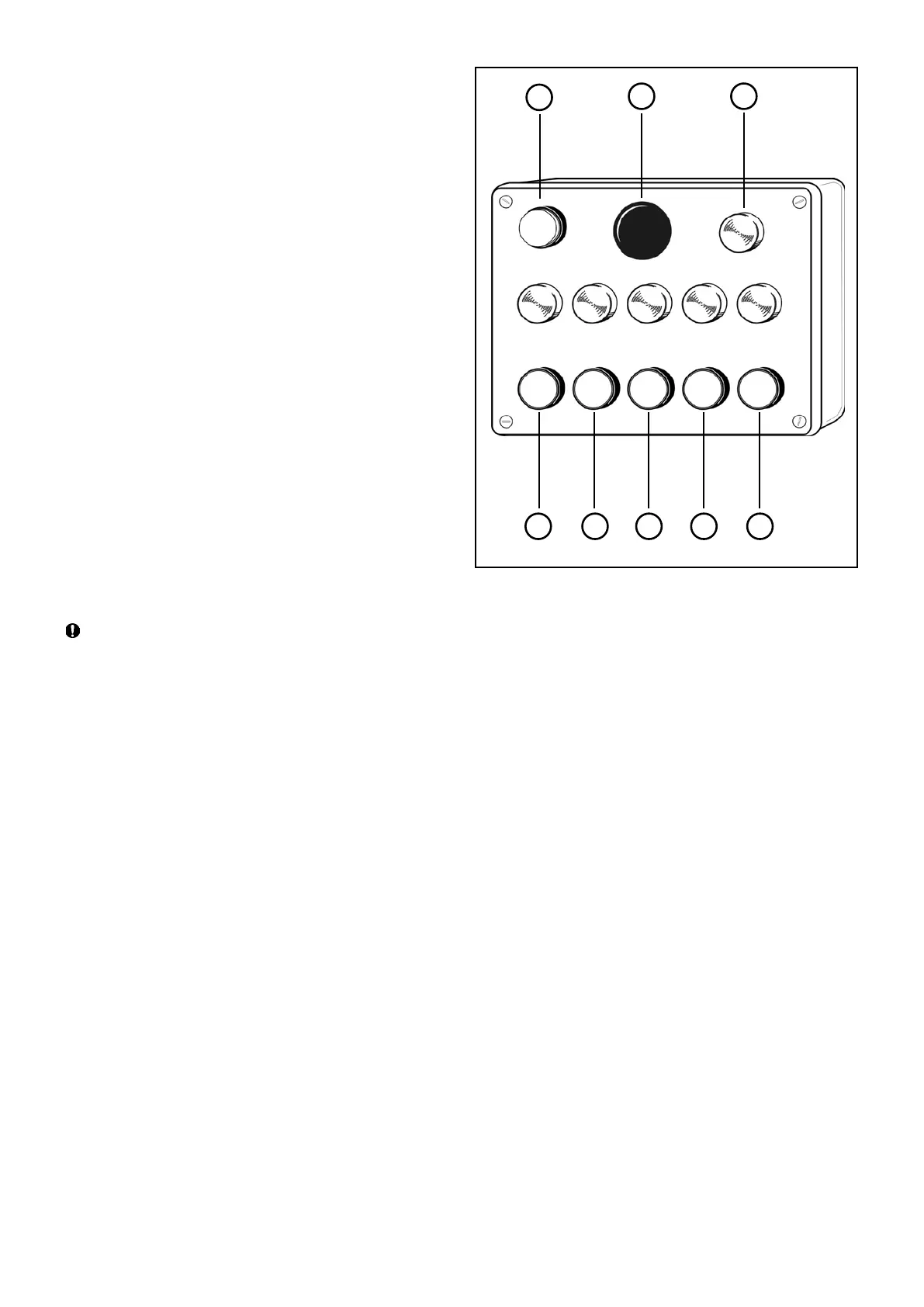
B1 Red: Stop button
B2 Red: Emergency stop button
B3 Black: Start button, lower cutter
B4 Black: Start button, right side cutter
B5 Black: Start button, left side cutter
B6 Black: Start button, upper cutter
B7 Black: Start, feed rollers
B8 Control lamp: Power connected
The red button B1 is a circuit breaker for all the motors. The red
button B2 is an emergency stop, and this button also stops all the
motors. When the emergency stop button has been activated,
you have to turn it 90° to be able to start the machine again.
Next to the emergency stop button there is a lamp indicating that
the power supply is connected. The lower button row starts the
machine’s motors. Above each button there is a lamp indicating
that the motor started by that button is running.
After every stop: wait at least 10 seconds before restarting
the machine, otherwise the fuse on the brake card will blow
or, in the worst case, you will damage the brake card.
B3 B4 B5 B6 B7
B1
B2
B8