16
Side cutters
Before opening the planer’s cover, ensure that the power is
disconnected and that the cutter heads are not rotating. Use
protective gloves. This is especially important when you are
loosening screws that are tightly screwed, or when you are
tightening the screws (see Safety Instructions). Be careful
of the planing knives. You can easily get cut by those, even
when touching them lightly.
The side cutters are located at the sides of the machine table.
The spindle axles are 30 mm (1.2”) in diameter, which is a
standard dimension. On delivery, the machine is equipped
with two universal cutter heads with planing knives, which can
readily be replaced by moulding knives. For safety reasons,
the cutters use conventional milling, i.e. the work piece is fed
against the rotation direction of the cutter. Due to this, the lock
nut and the spindle of the movable side cutter have to be left-
hand threaded.
After mounting of the side cutters:
Make sure there are no tools left inside the machine.
Make sure that all screws are reliably tightened.
Make sure that the cutter heads can rotate freely before
closing the protective cover.
Do you remember the safety instructions on pp.4-5?
Removing the side cutters
Cutter 2 (right side, stationary cutter): Using a 30 mm spanner
(supplied) and an adjustable spanner, loosen the nut on the
spindle. Screw off the nut and remove the cutter and spacers,
if any.
Cutter 3 (left side, movable cutter): Turn the crank so that the
cutter comes to its front position. The nut is loosened in the
same way as on cutter 2, with the only difference that the nut
of cutter 3 is left-hand threaded and therefore screwed in the
opposite direction.
Tip: Loosen the nuts on the side cutters by screwing them in the
same direction as their respective cutter rotate.
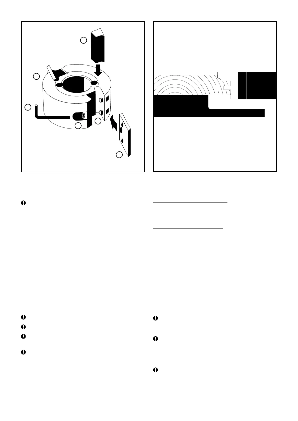
Replacing knives
Loosen the lock screw (B) with a 4 mm Allen key (C) (supplied),
and remove the chip breaker (D). Remove the knife (E) from
the dowel pins (F). Insert a new knife, and screw the lock
screws tight.
Make sure that the knives are turned the right way when
mounting them in the cutter head. The edge should be turned
towards the chip breaker.
Make sure that the rust protected chip deector before the
movable cutter does not run the risk of getting bent by the
unplaned edge of the work piece and due to this comes in
contact with the cutter. Be extra cautious when work pieces
of various widths are being processed.
Make sure that the cutter head can rotate freely, and
that there is a space of approx. 5 mm (0.2”) between the
outermost cutting diameter of the cutter and the chip deector
that works as a chip barrier behind the movable cutter.
C
A
D
B
F
E
6
7
8