11
- Fit the table support in the forks (four special nuts, two
threaded bars).
- Fit the struts to the outer sides of the table support (four
special nuts, two M8 washers, two threaded bars).
- Lift up the table support so that its rounded support surface
comes on a level with the machine table. If you are mounting
the feed tables single-handed: prop up the table support
in a reliable way, e.g. with boards. Place the feed table on
the table support and fold up the struts so that they reach
the feed table angle iron on the inner side of the feed
table. Fasten the struts and the feed table to the feed table
iron angle (two special nuts, two M8 washers, two M8x12
screws).
Instructions for basic setting of feed tables PH 260
- Loosen the screws holding the feed table iron angle (in front
of the machine table) just so much that the feed table can
move vertically.
- Place a level object on the adjusting plates in front of the
lower cutter, and adjust the whole front edge of the feed
table upwards until it is on a level with the adjusting plates,
then tighten the screws. (When adjusting the out-feed
table: measure against the machine table behind the upper
cutter.)
- Loosen the nuts holding the forks, so that the forks can move.
NB! Crush hazard when the screws are loosened. Remove
the boards propping up the table support, if you have used
such.
- Move the forks outwards, from the machine chassis, until
the outer edge of the feed table is on a level with the
machine table. To facilitate this adjustment you can use
wooden wedges, shims, or the like, between the forks and
the machine chassis. This helps pushing the forks from the
chassis until the desired feed table height is obtained. Make
sure that the forks are aligned with the table support. Tighten
the nuts.
Readjustment of feed tables PH 260
In some cases it can be of benet that the outer ends of the
feed tables are somewhat higher (1-10 mm or 0.04-0.4”) than
the machine table, to diminish the occurrence of in- and out-feed
snipes on the work pieces. This is especially important when thin
or soft work pieces are processed. The outer ends of the feed
table should never be lower than the machine table.
The in-feed table has to be adjusted when the cutting depth
of the lower cutter has been changed by adding or removing
adjusting plates.
Tip: The special nuts and Allen screws that hold the feed table
angle iron can be replaced by M10 nuts and M10 screws after
you have adjusted the feed table. When these screws are
tightened, the lateral play of the feed table will be reduced. This
can be of interest if, for instance, a longer (own-made) fence
for jointing operation with the rst side cutter is to be mounted
on the in-feed table. (Logosol supplies a ready-made fence for
jointing operation, which you t in the machine’s fence screw
plates, see Accessories.)
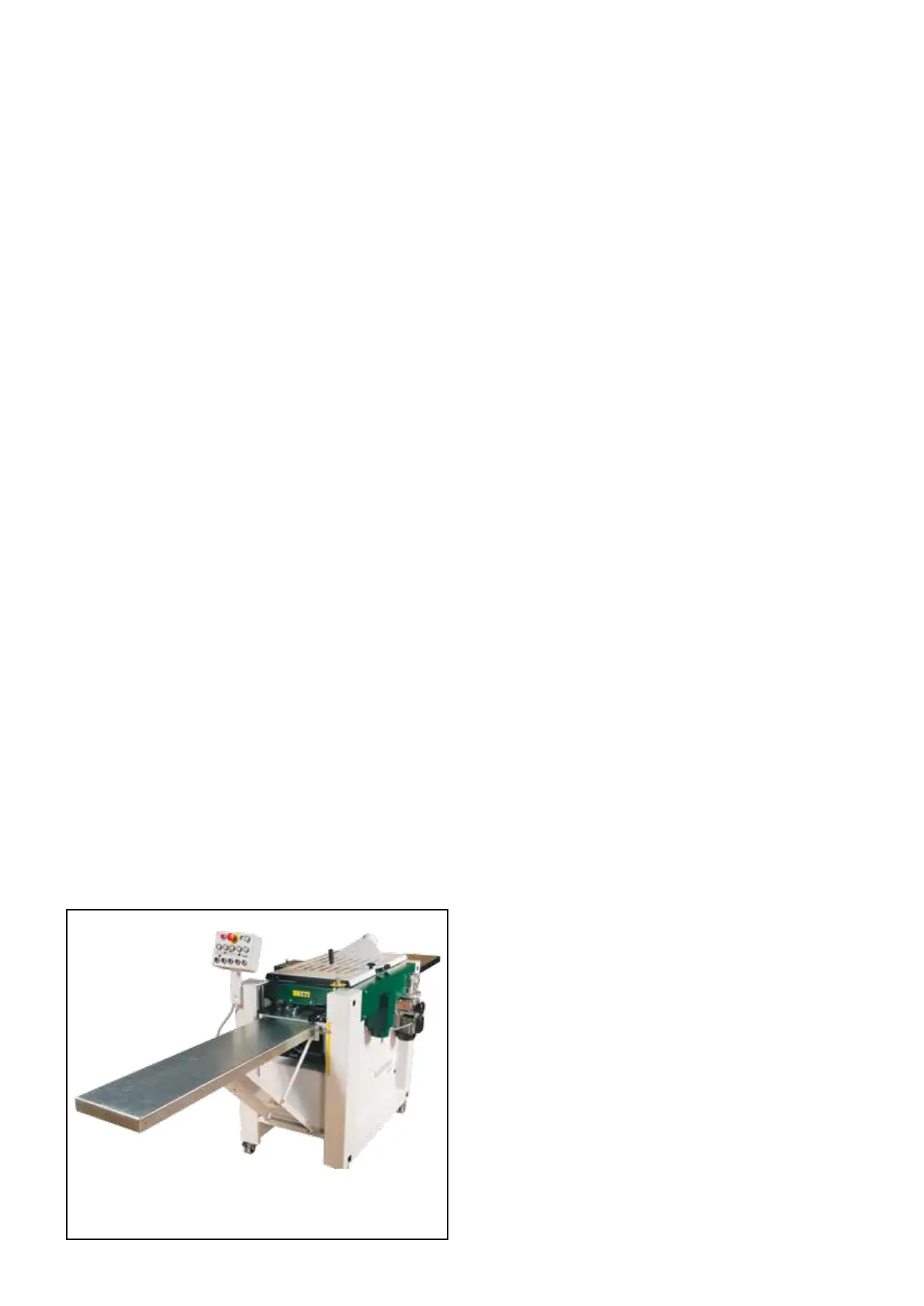
In- and Out-Feed Tables
Logosol can supply ready-made in- and out-feed tables made
of aluminium (1 feed table, ref. no. 7500-000-1000). You can
also make your own feed tables. To ensure that no knife marks
will be left on the ends of work pieces, it is vital that the in-feed
table, the machine table, and the out-feed table are exactly
level with each other.
Behind the front and rear edges of the machine table (20) there
are two threaded holes (M8). If you have made your own in- and
out-feed tables, those holes are intended for fastening the screw
plates (supplied) on which the feed tables are to be mounted.
Let the outer ends of the feed tables be supported by trestles
that are vertically adjustable. This way you get a good support
that can be adjusted when the height of the machine table is
changed. We recommend, however, that you use Logosol’s feed
tables to get the best results (see below).
Instructions for mounting feed tables PH 260
(These instructions are not complete. More detailed instructions
come with the feed tables).
The in- and out-feed tables are mounted the same way. The
instructions below describe mounting of the in-feed table. This
procedure is facilitated if you have someone that helps you.
Place a straight board in the machine and let it protrude over
the in-feed table. Secure the board by raising the machine table.
Loosen the screws and press the feed table up against the board.
Tighten. Loosen the screws and adjust the angle of the table.
- Fit the upper angle iron with screws in the threaded holes
behind the front edge of the machine table (two M8 washers,
two M8x20 screws).
- Fit the feed table iron angle to the upper iron angle (four M8
washers, two M8x20 screws, two M8 nuts).
- Fit the lower iron angle to the machine chassis, using the
M6 Allen screws that already are screwed in the holes in the
chassis.
- Fit the two forks in the lower angle iron’s oval holes (two M8
washers, two M8 nuts).
In- and out-feed tables, hoses, chip extractors, and many other
accessories are available from Logosol.