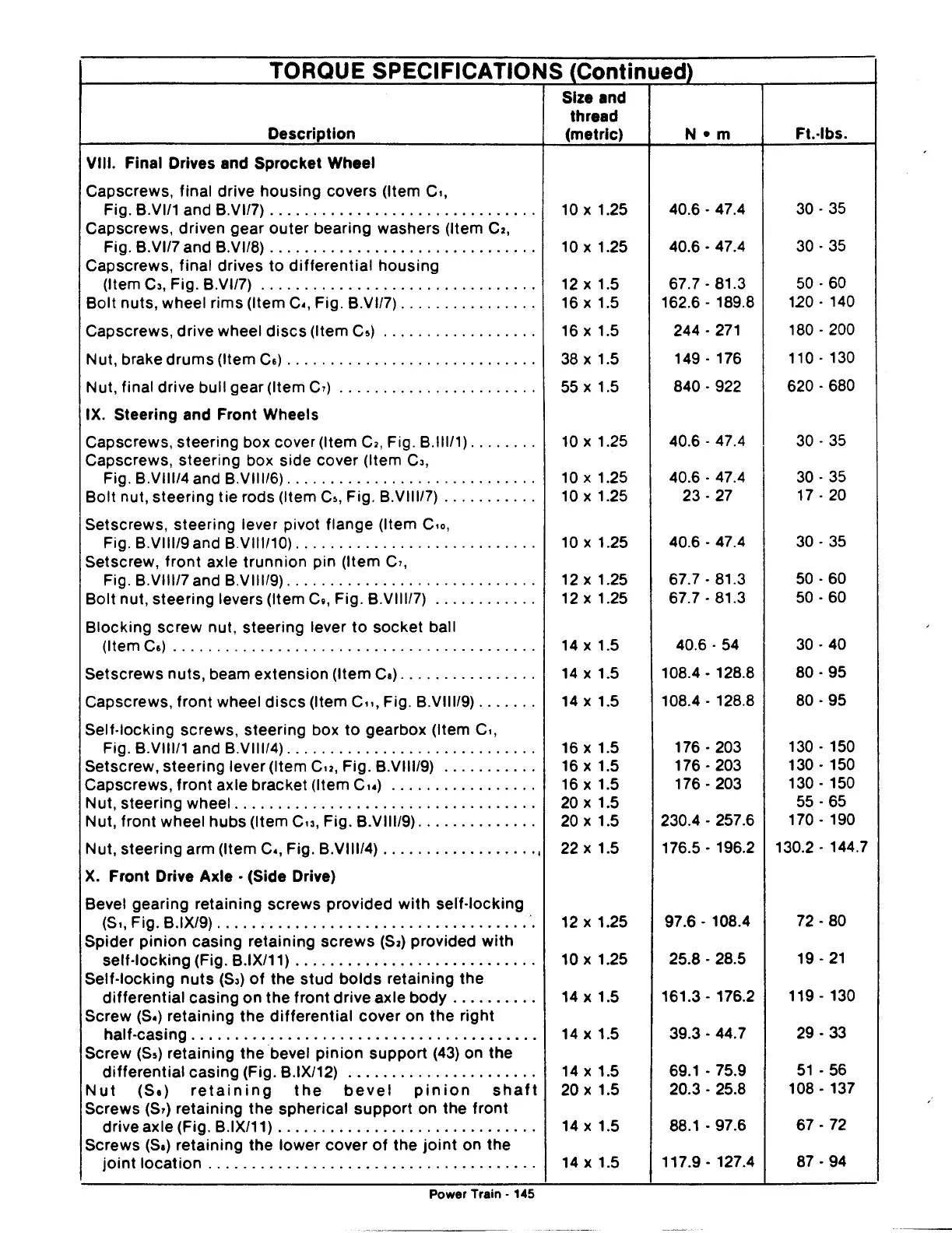
TORQUE
SPECIFICATIONS
(Continued)
Description
VIII. Final Drives and Sprocket Wheel
Capscrews, final drive
housing
covers (Item
c,,
Fig. B.VI/1 and B.VI/7)
..............................
.
Capscrews, driven gear
outer
bearing washers (Item
C2,
Fig. B.VI/7 and B.VI/8)
..............................
.
Capscrews, final drives
to
differential
housing
(Item
C3,
Fig. B.VI/7)
...............................
.
Bolt nuts, wheel rims (Item
c~.
Fig. B.VI/7)
...............
.
Capscrews, drive wheel
discs
(Item
C5)
.................
.
Nut, brake
drums
(Item
C&)
............................
.
Nut, final drive bull gear (Item
C1)
......................
.
IX. Steering and Front Wheels
Capscrews, steering box cover (Item
C2,
Fig. B.lll/1)
.......
.
Capscrews, steering box side cover (Item
C3,
Fig. B.VIII/4 and B.VIII/6)
............................
.
Bolt nut, steering tie rods (Item
C5,
Fig. B.VIII/7)
..........
.
Setscrews, steering lever pivot flange (Item
c,o,
Fig. B.VIII/9 and B.VIII/10)
...........................
.
Setscrew, front axle
trunnion
pin (Item
C1,
Fig. B.VIII/7 and B.VIII/9)
............................
.
Bolt nut, steering levers (Item
C11,
Fig. B.VIII/7)
...........
.
Blocking screw nut, steering lever
to
socket ball
(Item
C&)
.........................................
.
Setscrews nuts, beam extension (Item
Ca)
...............
.
Capscrews, front wheel
discs
(Item c,,, Fig. B.VIII/9)
......
.
Self-locking screws, steering box
to
gearbox (Item
c,,
Fig. B.VIII/1 and B.VIII/4)
............................
.
Setscrew, steering lever (Item
Cu,
Fig. B.VIII/9)
..........
.
Capscrews,
front
axle bracket (Item
Cu)
................
.
Nut, steering wheel
..................................
.
Nut, front wheel
hubs
(Item
Cu,
Fig. B.VIII/9)
.............
.
Nut, steering arm (Item
c~.
Fig. B.VIII/4)
..................
,
X.
Front Drive Axle • (Side Drive)
Bevel gearing retaining screws provided
with
self-locking
Size and
thread
(metric)
10
X 1.25
10
X 1.25
12
X 1.5
16
X 1.5
16
X 1.5
38
X 1.5
55
X 1.5
10
X 1.25
10
X 1.25
10
X 1.25
10
X 1.25
12
X 1.25
12
X 1.25
14
X 1.5
14
X 1.5
14
X 1.5
16
X 1.5
16
X 1.5
16
X 1.5
20
X 1.5
20
X 1.5
22
X 1.5
(S,, Fig. B.IX/9)
....................................
·.
12 X 1.25
Spider
pinion
casing retaining
screws
($2)
provided
with
self-locking (Fig. B.IX/11) . . . . . . . . . . . . . . . . . . . . . . . . . . . . 10 x 1.25
Self-locking
nuts
(S3)
of
the stud
bolds
retaining the
differential
casing on the
front
drive axle
body
. . . . . . . . . .
14
x 1.5
Screw
(S~)
retaining the
differential
cover on the right
half-casing........................................
14
x 1.5
Screw
(55) retaining the bevel
pinion
support
(43)
on the
differential
casing (Fig. B.IX/12) . . . . . . . . . . . . . . . . . . . . . .
14
x 1.5
Nut
(Sa)
retaining
the
bevel
pinion
shaft
20
x 1.5
Screws
($1)
retaining the spherical
support
on the
front
drive axle (Fig. B.IX/11) . . . . . . . . . . . . . . . . . . . . . . . . . . . . . .
14
x 1.5
Screws
(Sa)
retaining the lower cover
of
the
joint
on the
joint
location
. . . . . . . . . . . . . . . . . . . . . . . . . . . . . . . . . . . . . .
14
x 1.5
Power
Traen
- 145
40.6.
47.4
40.6.
47.4
67.7-81.3
162.6-
189.8
244.
271
149.
176
840.
922
40.6-
47.4
40.6.
47.4
23.27
40.6-
47.4
67.7-81.3
67.7-81.3
40.6.
54
108.4 - 128.8
108.4-
128.8
176-
203
176-
203
176-
203
230.4-
257.6
176.5- 196.2
97.6-
108.4
25.8-
28.5
161.3-
176.2
39.3-44.7
69.1
- 75.9
20.3-
25.8
88.1-
97.6
117.9 - 127.4
Ft.-lbs.
30.35
30.35
50.60
120.
140
180 -
200
110 - 130
620-
680
30.
35
30-35
17-
20
30-35
50-60
50-60
30-40
80-95
80-95
130-
150
130-
150
130-
150
55-65
170-
190
130.2- 144.7
72-80
19-
21
119-
130
29-33
51
-56
108-
137
67-72
87-94