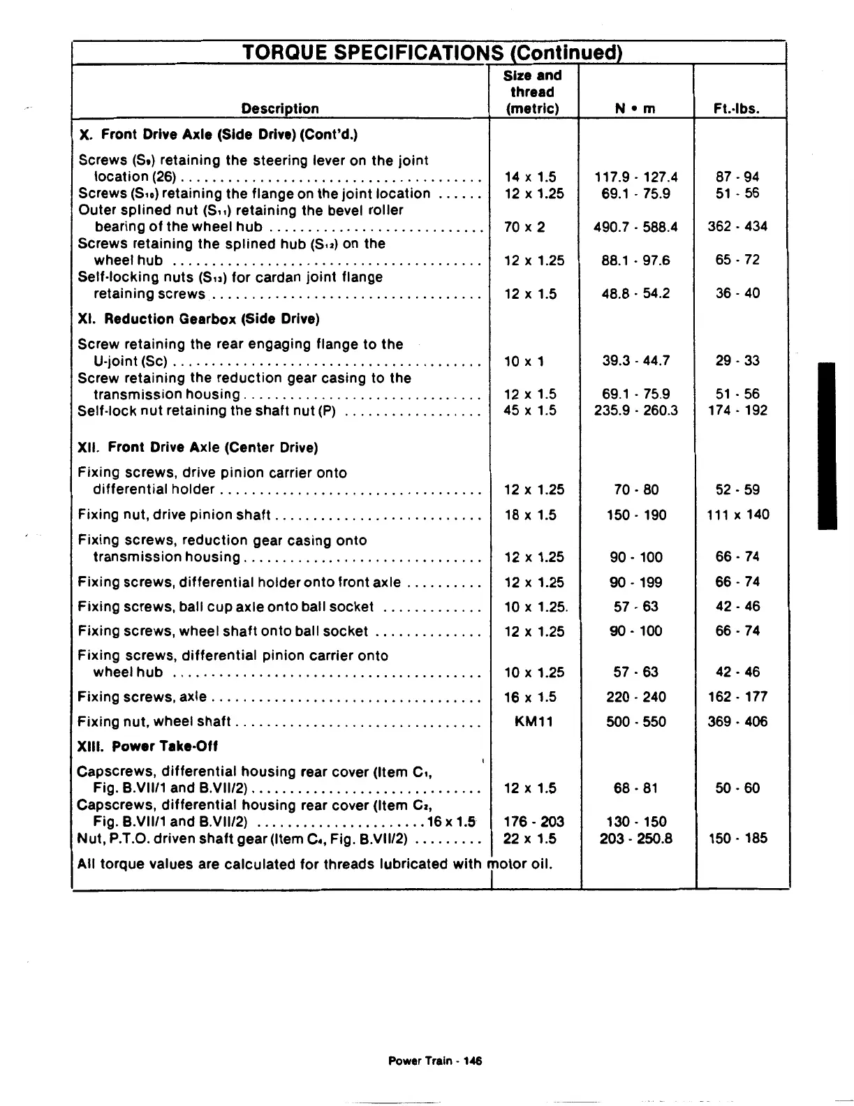
TORQUE SPECIFICATIONS (Continued)
Description
X.
Front Drive Axle (Side Drive) (Cont'd.)
Screws (St) retaining
the
steering lever on the
joint
Size and
thread
(metric)
location
(26)
. . . . . . . . . . . . . . . . . . . . . . . . . . . . . . . . . . . . . . .
14
x 1.5
Screws
(S,o)
retaining
the
flange on the
joint
location . . . . . .
12
x 1.25
Outer
splined
nut (S,,) retaining the bevel roller
bearing
of
the wheel
hub
. . . . . . . . . . . . . . . . . . . . . . . . . . . . 70 x 2
Screws retaining
the
splined hub (Su) on the
wheel
hub
. . . . . . . . . . . . . . . . . . . . . . . . . . . . . . . . . . . . . . . . 12 x 1.25
Self-locking
nuts
(Su) for cardan
joint
flange
retaining screws . . . . . . . . . . . . . . . . . . . . . . . . . . . . . . . . . . .
12
x 1.5
XI. Reduction Gearbox (Side Drive)
Screw retaining the rear engaging flange
to
the
U-joint (Sc) . . . . . . . . . . . . . . . . . . . . . . . . . . . . . . . . . . . . . . . . 10 x 1
Screw retaining the reduction gear casing to the
transmission
housing
. . . . . . . . . . . . . . . . . . . . . . . . . . . . . . .
12
x 1.5
Self-lock
nut
retaining
the
shaft nut
(P)
. . . . . . . . . . . . . . . . . .
45
x 1.5
XII. Front Drive Axle (Center Drive)
Fixing screws, drive
pinion
carrier
onto
differential
holder
.................................
.
12
X 1.25
Fixing
nut,
drive
pinion
shaft
..........................
.
18
X 1.5
Fixing screws, reduction gear casing
onto
transmission
housing
..............................
.
12
X 1.25
Fixing
screws,
differential
holder
onto
front axle
.........
.
12
X 1.25
Fixing
screws, ball
cup
axle
onto
ball socket
............
.
10
X 1.25.
Fixing screws, wheel
shaft
onto
ball socket
.............
.
12
X 1.25
Fixing screws,
differential
pinion carrier
onto
wheel
hub
.......................................
.
10
X 1.25
Fixing screws, axle
..................................
.
16
X 1.5
Fixing nut, wheel
shaft
...............................
. KM11
XIII. Power Take-Off
I
Capscrews,
differential
housing
rear cover (Item
c,,
Fig. B.VII/1 and B.VII/2)
.............................
.
12
X 1.5
Capscrews,
differential
housing
rear cover (Item
Cz,
Fig. B.VII/1 and B.VII/2)
......................
16
x 1.5
176.203
Nut,
P.T.O. driven
shaft
gear (Item
c.,
Fig. B.VII/2)
........
.
22
X 1.5
All
torque values are calculated for threads lubricated
with
jotor
oil.
Power Train - 146
117.9.
127.4
69.1.
75.9
490.7 . 588.4
88.1.
97.6
48.8.
54.2
39.3.
44.7
69.1
. 75.9
235.9 . 260.3
70.80
150.
190
90.
100
90.
199
57.63
90.
100
57.63
220.240
500.550
68.81
130.
150
203.
250.8
Ft.-lbs.
87.94
51
.
56
362.
434
65.
72
36.40
29.33
51.
56
174.
192
52.59
111
X 140
66.
74
66.74
42.46
66.74
42.46
162.
177
369.
406
50.60
150.
185