Recorder Overview3
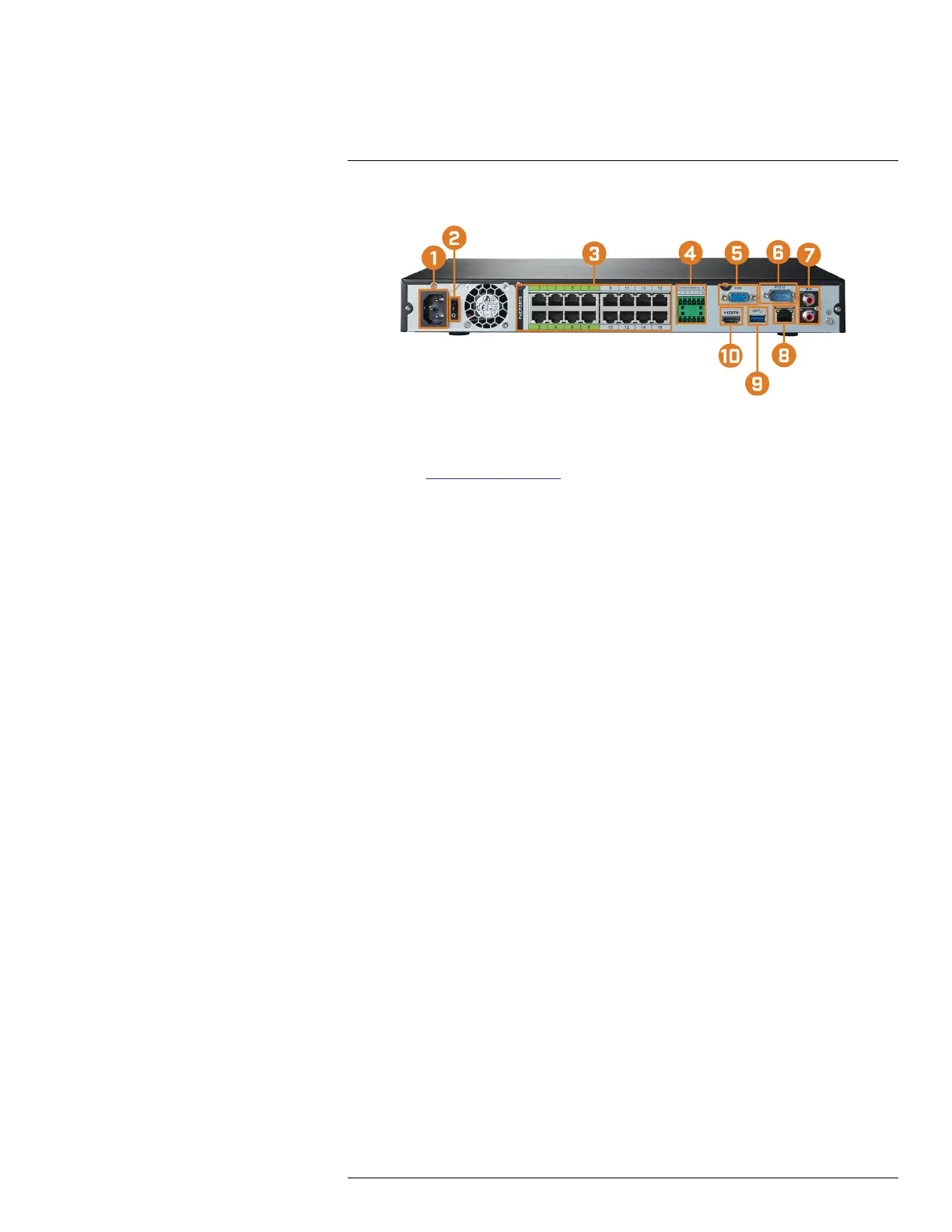
3.2 Back Panel
1. Power Input: Connect the included AC power cable.
2. Power Switch: Press to power the system on / off.
3. PoE Video Inputs: Connect Lorex IP cameras to the system. For a full list of compatible cam-
eras, visit lorex.com/compatibility.
4. Alarm Block: Connect alarm / sensor devices (not included).
5. VGA: Connect a VGA monitor (not included) to view the system interface.
6. RS232: Connect access control systems (not included).
7. AUDIO IN/OUT:
• Connect an external microphone to the AUDIO IN port for single-channel audio recording.
• Connect an external speaker to the AUDIO OUT port to hear system audio
• For full details on connecting external audio devices, see 18 Connecting Audio Devices,
page 111.
8. LAN: Connect the included RJ45 Ethernet cable from the recorder to your router for remote
connectivity and automatic firmware updates.
9. USB Port: Connect a USB mouse (included) to control the system, or a USB flash drive (not
included) for data backup or manual firmware updates.
10. HDMI: Connect to an HDMI monitor or TV (not included) using the included HDMI cable to
view the system interface.
#LX400113; r. 3.0/56326/56332; en-US 6

 Loading...