4.2.6 Setting a Frequency Reference via RS-485 Communication
Control the inverter with upper-level controllers, such as PCs or PLCs, via RS-485
communication. Set the Frq (Frequency reference source) code (code 07) in the DRV
group to 6 (Int 485) and use the RS-485 signal input terminals (S+/S-/SG) for
communication. Refer to 7 RS-485 Communication features on page 349.
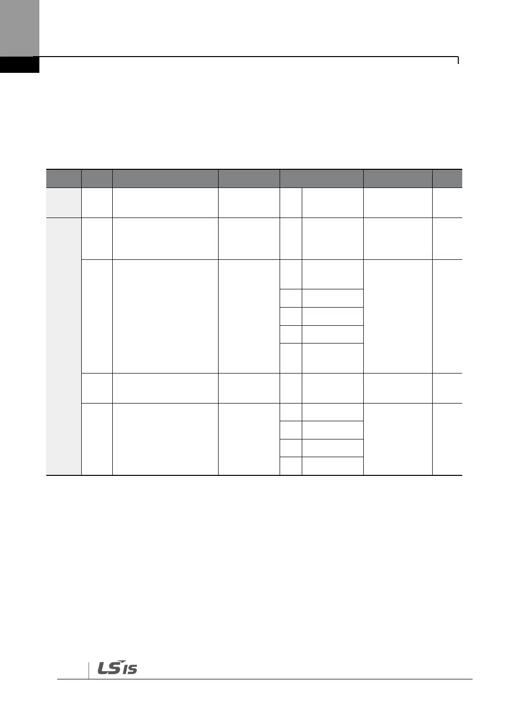
Frequency reference
source
Integrated RS-485
communication
inverter ID
Integrated
communication
protocol
Integrated
communication speed
Integrated
communication frame
configuration
*If AP1-40 is set to ‗4(Serve Drv)‘, MaxComID is ‗8‘, and if COM-02 is set to ‗4(BACnet),
MaxComID is ‗127‘. Otherwise MaxComID is ‗250‘.
** COM-02 is automatically set to ‗6(Modbus Master)‘ when AP1-40 is set to ‗2 or 3‘.
Otherwise a user can set the parameter value at user‘s choice.