4.13 V/F (Voltage/Frequency) Control
Configure the inverter‘s output voltages, gradient levels, and output patterns to achieve a
target output frequency with V/F control. The amount of of torque boost used during low
frequency operations can also be adjusted.
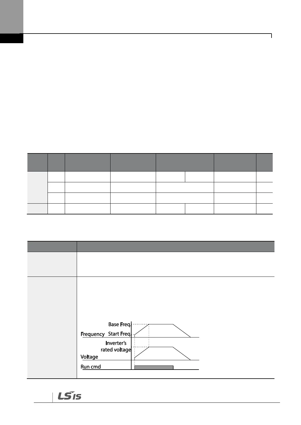
4.13.1 Linear V/F Pattern Operation
A linear V/F pattern configures the inverter to increase or decrease the output voltage at a
fixed rate for different operation frequencies based on V/F characteristics. A linear V/F
pattern is partcularly useful when a constant torque load is applied.
Linear V/F Pattern Setting Details
Sets the base frequency. A base frequency is the inverter‘s output
frequency when running at its rated voltage. Refer to the motor‘s rating
plate to set this parameter value.
Sets the start frequency. A start frequency is a frequency at which the
inverter starts voltage output. The inverter does not produce output voltage
while the frequency reference is lower than the set frequency. However, if a
deceleration stop is made while operating above the start frequency, output
voltage will continue until the operation frequency reaches a full-stop (0 Hz).