RS-485 Communication Features
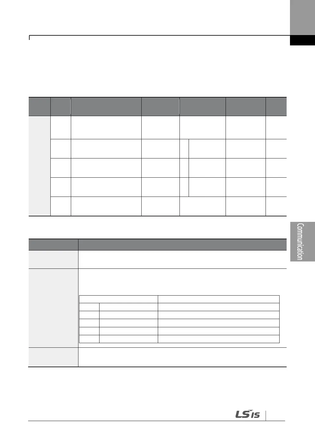
7.2.2 Setting Communication Parameters
Before proceeding with setting communication configurations, make sure that the
communication lines are connected properly. Turn on the inverter and set the
communication parameters.
Built-in communication
inverter ID
Built-in communication
protocol
Built-in communication
speed
Built-in communication
frame setting
Transmission delay after
reception
Communication Parameters Setting Details
Sets the inverter station ID between 1 and MaxComID.
Select one of the four built-in protocols: Modbus-RTU, LS INV 485, BACnet
or Metasys-N2.
Modbus-RTU compatible protocol
Dedicated protocol for the LS inverter
Dedicated protocol for ModBus Master
Set a communication setting speed up to 115,200 bps.
The maximum setting range changes depending on the protocol.
If AP1-40 is set to ‗4(Serve Drv)‘, MaxComID is ‗8‘, and if COM-02 is set to ‗4(BACnet),
MaxComID is ‗127‘. Otherwise MaxComID is ‗250‘.