Learning Advanced Features
AP1-61
AP1-62
AP1-63
AP1-64
AP1-65
Max Freq
Frequency
AP1-70
AP1-71
AP1-72
Aux Motor 1
Aux Motor 2
Aux Motor 3
Aux Motor 4
Aux Motor 5
Feedback
AP1-71
AP1-71
AP1-72
AP1-62
AP1-63
0%
100%
Priority at the moment
M2 M1 M3 /
M4 M5
Priority at the moment
M1 M2 M3 /
M4 M5
Priority at the moment
M3 M2 M1 /
M4 M5
Priority at the moment
M3 M2 M1 /
M4 M5
5min
10min
AP1-61
30min
Operation time
M1(30min) / M2(25min) /
M3(20min)
Supposing its operating in
less than 1 minute
Output
frequency
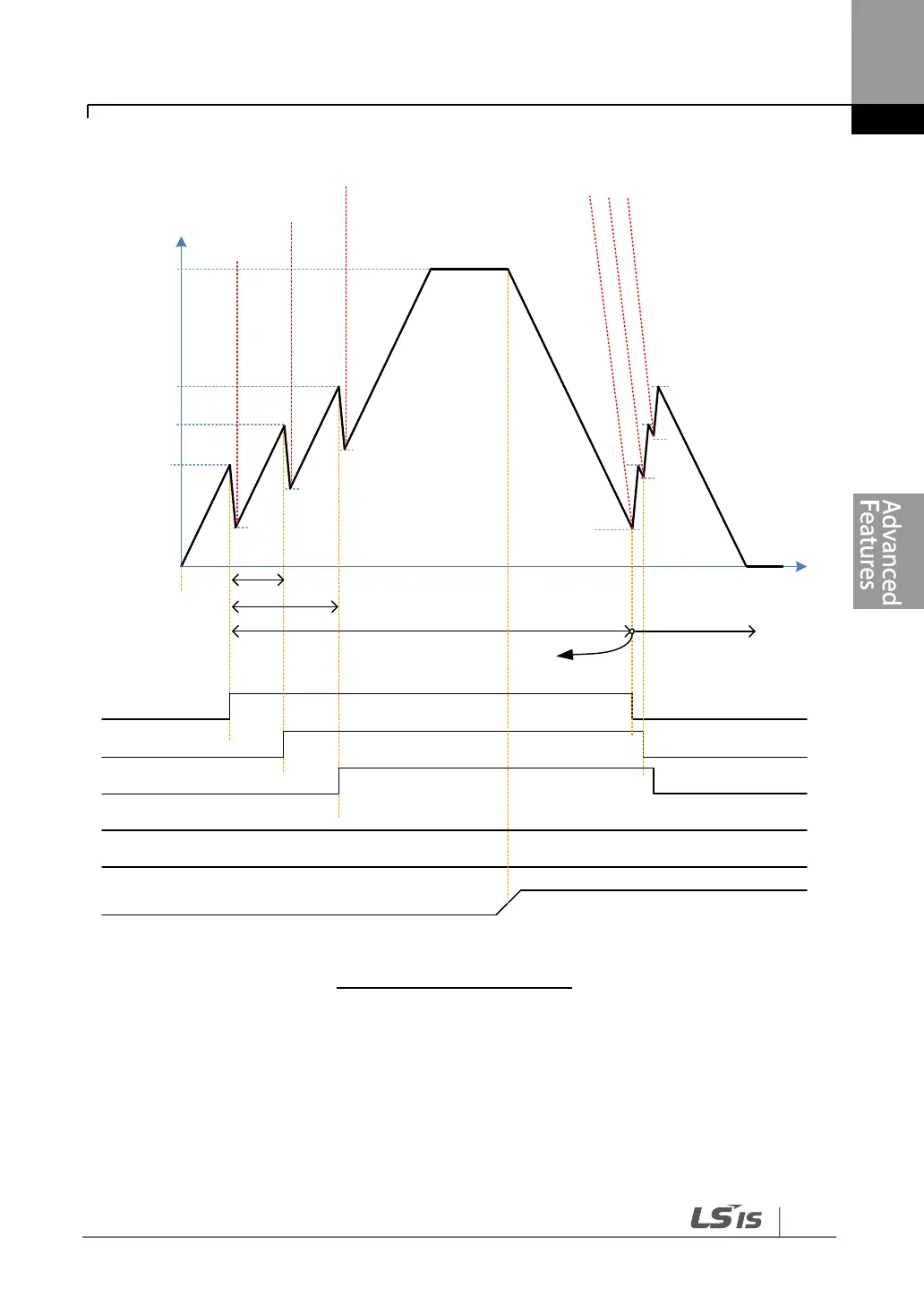
MMC Basic operation(OP Time Order)
The following diagram is an operation graph based on the start and stop delay times set at AP1-
53 (Aux start DT) and AP1-54 (Aux stop DT). When the start or stop frequencies are reached,
the auxiliary motor waits for the time set at AP1-53 (Aux start DT) or AP1-54 (Aux stop DT)
before it starts or stops.