Maintenance
STYLEREF Chapter \* MERGE
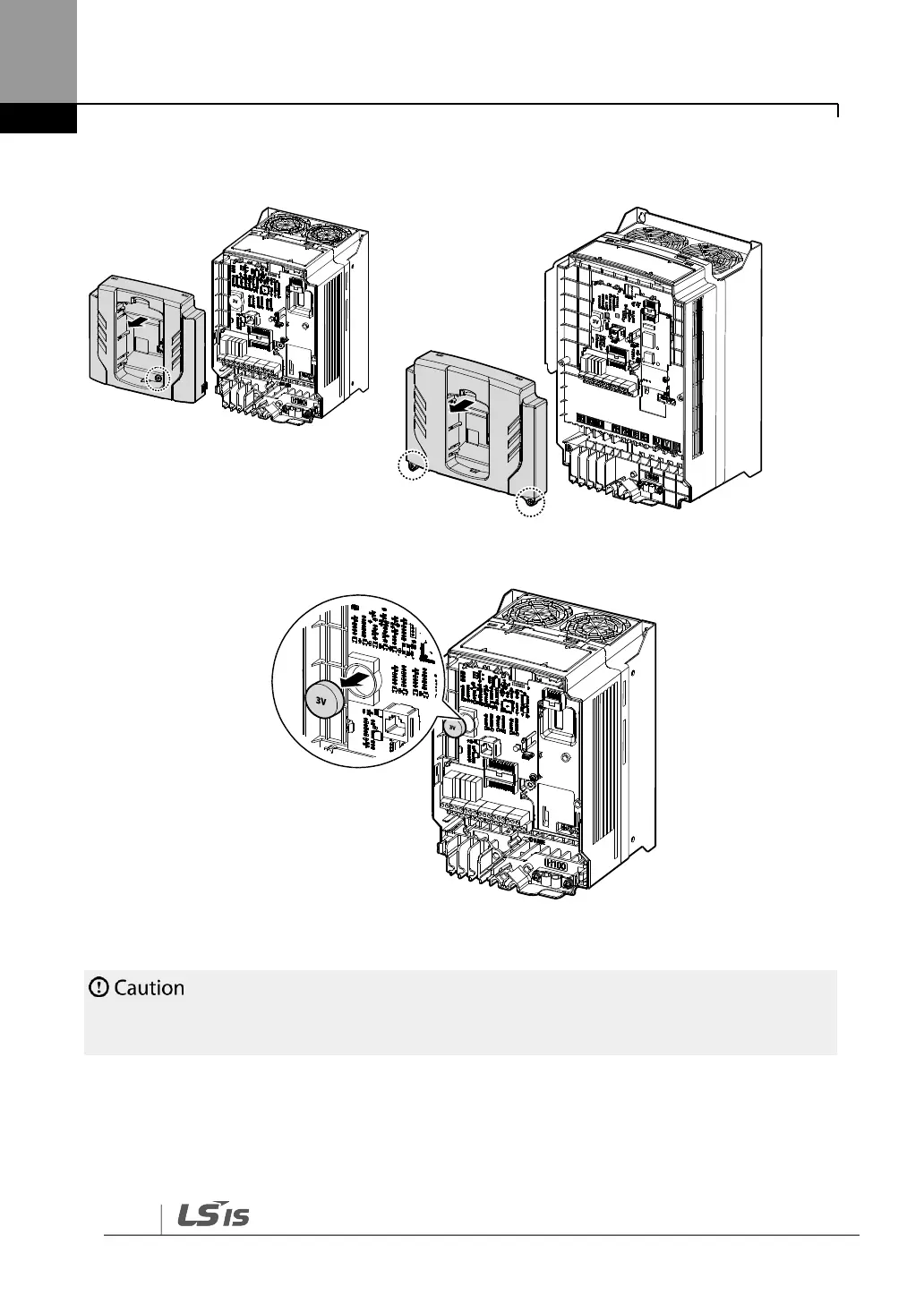
4 Loosen the screws securing the front cover, and remove the front cover by lifting it. The
main PCB is exposed.
5 Locate the RTC battery holder on the main PCB, and replace the battery.
6 Reattach the front cover, the power cover, and the keypad back onto the inverter body
Ensure that the inverter is turned off and DC link voltage has dropped to a safe level before
opening the terminal cover and installing the RTC battery.


 To Next Page