8-12
z
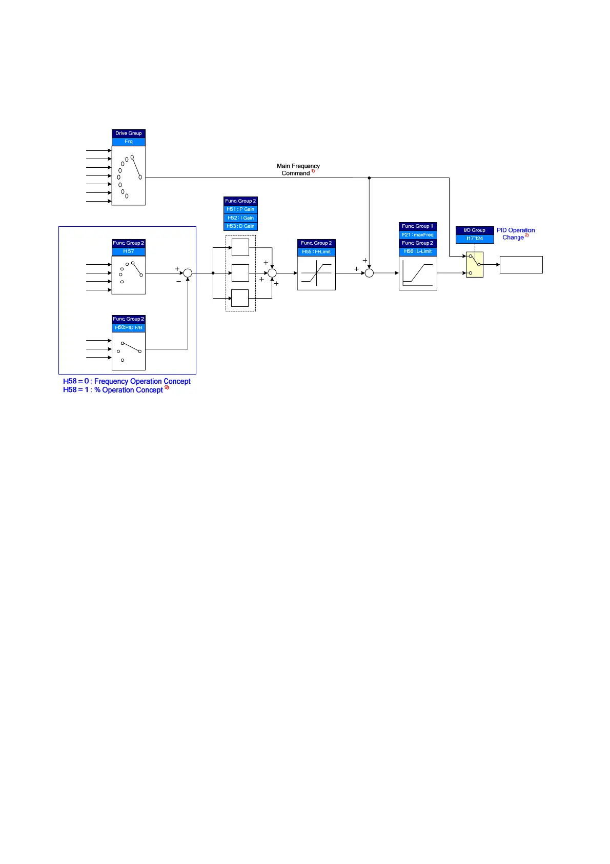
Process PID drive (H54=1)
0
1
2
PID F/B Select
PID Gain
PID Limit
PID Command
Select
PID REF
PID FBK
PID Output
Frequency
0
1
2
3
4
KeyPad-1/-2
V1_2(0~10V)
I(0~20mA)
Communication
V1_2(0~10V)
I(0~20mA)
Communication
1st/2nd
Frequency Select
KeyPad-1/-2
V1_1(-10~10V)
V1_2(0~10V)
I(0~20mA)
V1_1 + I
V1_2 + I
Communication
Output Freq. Limit
PID OUT1
3)
PID OUT2
4)
K
P
K
I
/s
K
D
s
Mult Function
Input
0
1
2
3
4
5
6
7
1) Speed command is the frequency (FRQ=8, except Up/Down) set by FRQ/FRQ2 and real output
frequency is sum of speed command, PID OUT1 and PID OUT2.
2) If PID switching drive is selected,
3) PID OUT1’s polarity is double. It is limited H55 (PID upper Limit).
4) Real output frequency PID OUT2 is limited by F21 (MaxFreq) and H56 (PID lower Limit)
Other operation is same with the Normal PID.
z Sleep & Wake-up
In the night for example, if output frequency of PID control is maintained over sleep delay
time(H61) due to not enough flux, Sleep function becomes sleep mode automatically and
inverter is stop. Under sleep mode, if error of PID Reference and Feedback is over H63(Wake-
up Level), Sleep mode is released and the inverter restarts.
If stop command is input, Sleep mode is released

 Loading...

