9-42
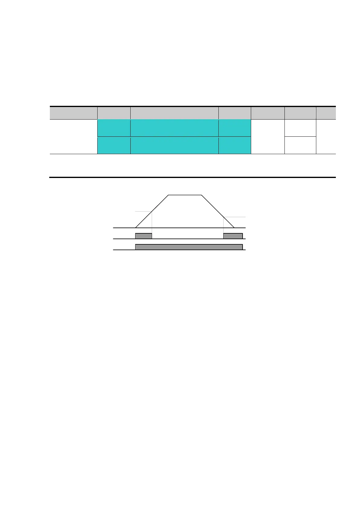
z 4: FDT-5
Activated as B contact contrast to FDT-4.
Active condition:
Accel time: Run Frequency >= FDT Level
Decel time: Run Frequency > (FDT Level – FDT Bandwidth/2)
Group Display Parameter Name Setting Range Default Unit
I/O group
I52
[Detected Frequency
level]
-
0 ~ 400
30.00
Hz
I53
[Detected Frequency
Bandwidth]
-
10.00
Cannot be set above Max frequency (F21).
When setting I52 and I53 to 30.0Hz and 10.0 Hz, respectively
z 5: Overload (OLt)
Refer to page 10-2.
z 6: Inverter Overload (IOLt)
Refer to page 10-6.
z 7: Motor stall (STALL)
Refer to page 10-3.
z 8: Over voltage trip (Ovt)
Activated when over voltage trip occurs due to DC link voltage exceeded
400Vdc for 200V class and 820Vdc for 400V class.
z 9: Low voltage trip (Lvt)
Activated when low voltage trip occurs due to DC link voltage under
180Vdc for 200V class and 360Vdc for 400V class.
z 10: Inverter heatsink overheat (OHt)
Activated when the heatsink is overheated.
z 11: Command loss
Activated when Analog (V1,I) and RS485 communication commands are
lost.
Freq.
MO
Run
command
25Hz
30Hz

 Loading...

