11-10
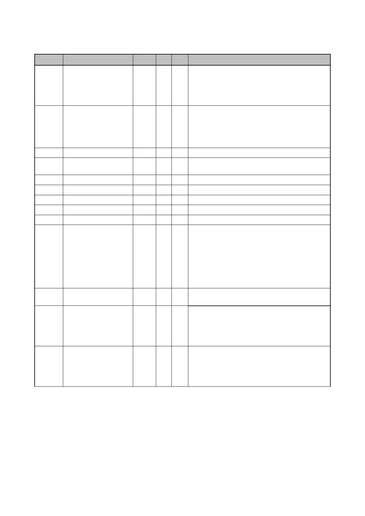
Address Parameter Scale Unit R/W
Data value
0x0010 Input terminal status
BIT 4: P5
BIT 5: P6
BIT 6: P7
BIT 7: P8
0x0011 Output terminal status
R
BIT 0~3: Not Used
BIT 4: MO (Multi-Output with OC)
BIT 5~6: Not Used
BIT 7: 3ABC
0x0012 V1 0~3FF R Value corresponding to 0V ~ +10V
0x0013 V2 0~3FF R
Value corresponding to 0V ~ -10V input when
Setting FreqMode to 2
0x0014 I 0~3FF R Value corresponding to 0 ~ 20mA input
0x0015 RPM R See Function List.
0x001A Unit display
R
Not Used
0x001B Pole number
R
Not Used
0x001C Custom Version
R
Not Used
0x001D Trip information-B R
BIT 0: COM (I/O Board Reset)
BIT 1: FLTL
BIT 2: NTC
BIT 3: REEP
BIT 4: OC2
BIT 5: NBR
BIT 6 ~ 15: Not Used
0x001E PID Feedback
Hz
/%
W
Writes feedback amount when feedback is set
by communication in PID drive.
0x0100
~
0x0107
Read address register
R
0x0100: 166 0x0101: 167
0x0102: 168 0x0103: 169
0x0104: 170 0x0105: 171
0x0106: 172 0x0107: 173
0x0108
~
0x010F
Write address register
W
0x0108: 174 0x0109: 175
0x010A: 176 0x010B: 177
0x010C: 178 0x010D: 179
0x010E: 180 0x010F: 181
Note 1) The changed value in Common area affects the current setting but returns to the previous
setting when power is cycled or Inverter is reset. However, changing value is immediately reflected
in other parameter groups even in the case of Reset or Power On/Off.
Note 2) S/W version of Common area is displayed in 16 bit, while that of parameter area is
displayed in 10 bit.

 Loading...

