5-6
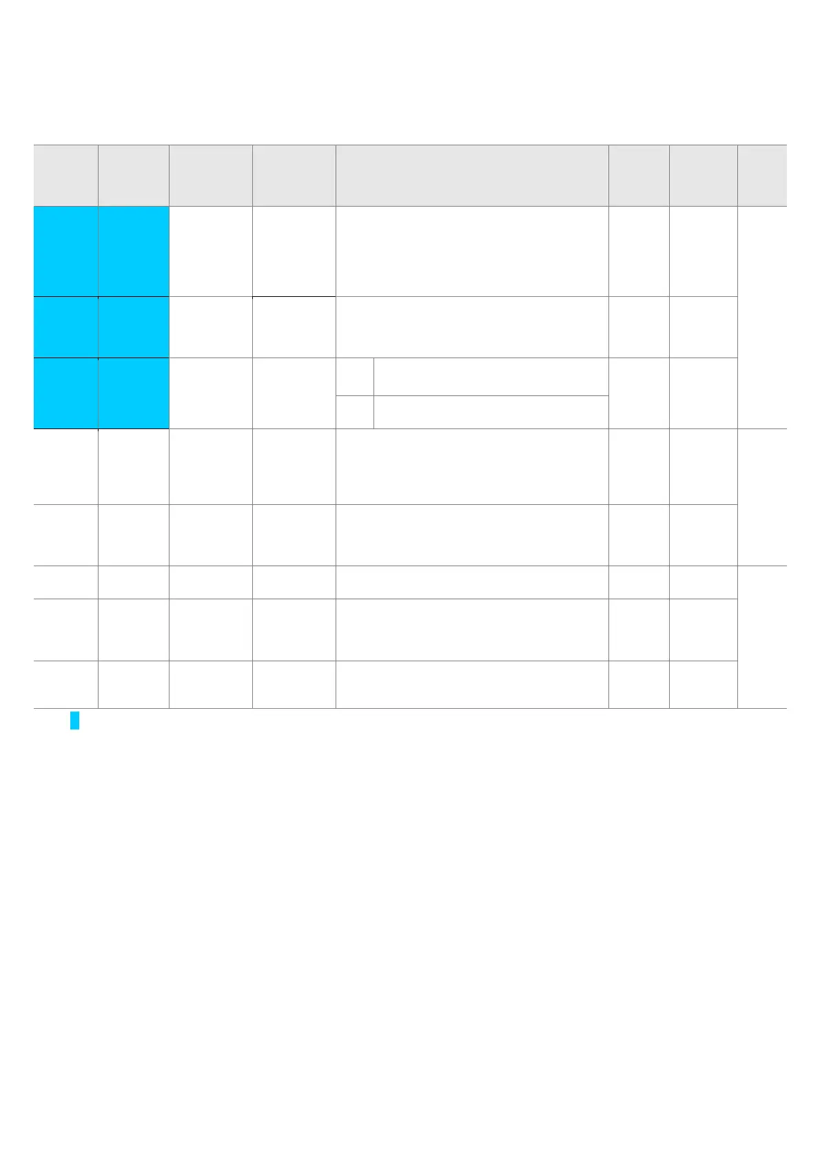
z Function group 1
LED
display
Address
for
communic
ation
Parameter
name
Min/Max
range
Description
Factory
defaults
Adj.
during
run
Page
F51
1)
A233 [Electronic
thermal
level for 1
minute]
50 ~ 200
[%]
This parameter sets max current capable of
flowing to the motor continuously for 1 minute.
The set value is the percentage of H33 –
[Motor rated current].
It cannot be set below F52 –[Electronic thermal
level for continuous].
150 0 10-1
F52
A234 [Electronic
thermal
level for
continuous]
50 ~ 150
[%]
This parameter sets the amount of current to
keep the motor running continuously.
It cannot be set higher than F51 – [Electronic
thermal level for 1 minute].
100 0
F53
A235 [Motor
cooling
method]
0 ~ 1 0
Standard motor having cooling fan
directly connected to the shaft
0 0
1 A motor using a separate motor to
power a cooling fan.
F54
A236 [Overload
warning
level]
30 ~ 150
[%]
This parameter sets the amount of current to
issue an alarm signal at a relay or multi-
function output terminal (see I54, I55).
The set value is the percentage of H33- [Motor
rated current].
150 0 10-2
F55 A237 [Overload
warning
time]
0 ~ 30 [Sec] This parameter issues an alarm signal when
the current greater than F54- [Overload
warning level] flows to the motor for F55-
[Overload warning time].
10 0
F56 A238 [Overload
trip select]
0 ~ 1 This parameter turns off the inverter output
when motor is overloaded.
1 0 10-2
F57 A239 [Overload
trip level]
30 ~ 200
[%]
This parameter sets the amount of overload
current.
The value is the percentage of H33- [Motor
rated current].
180 0
F58 A23A [Overload
trip time]
0 ~ 60 [Sec] This parameter turns off the inverter output
when the F57- [Overload trip level] of current
flows to the motor for F58- [Overload trip time].
60 0
1)
: Set F50 to 1 to display this parameter.

 Loading...

