5-5
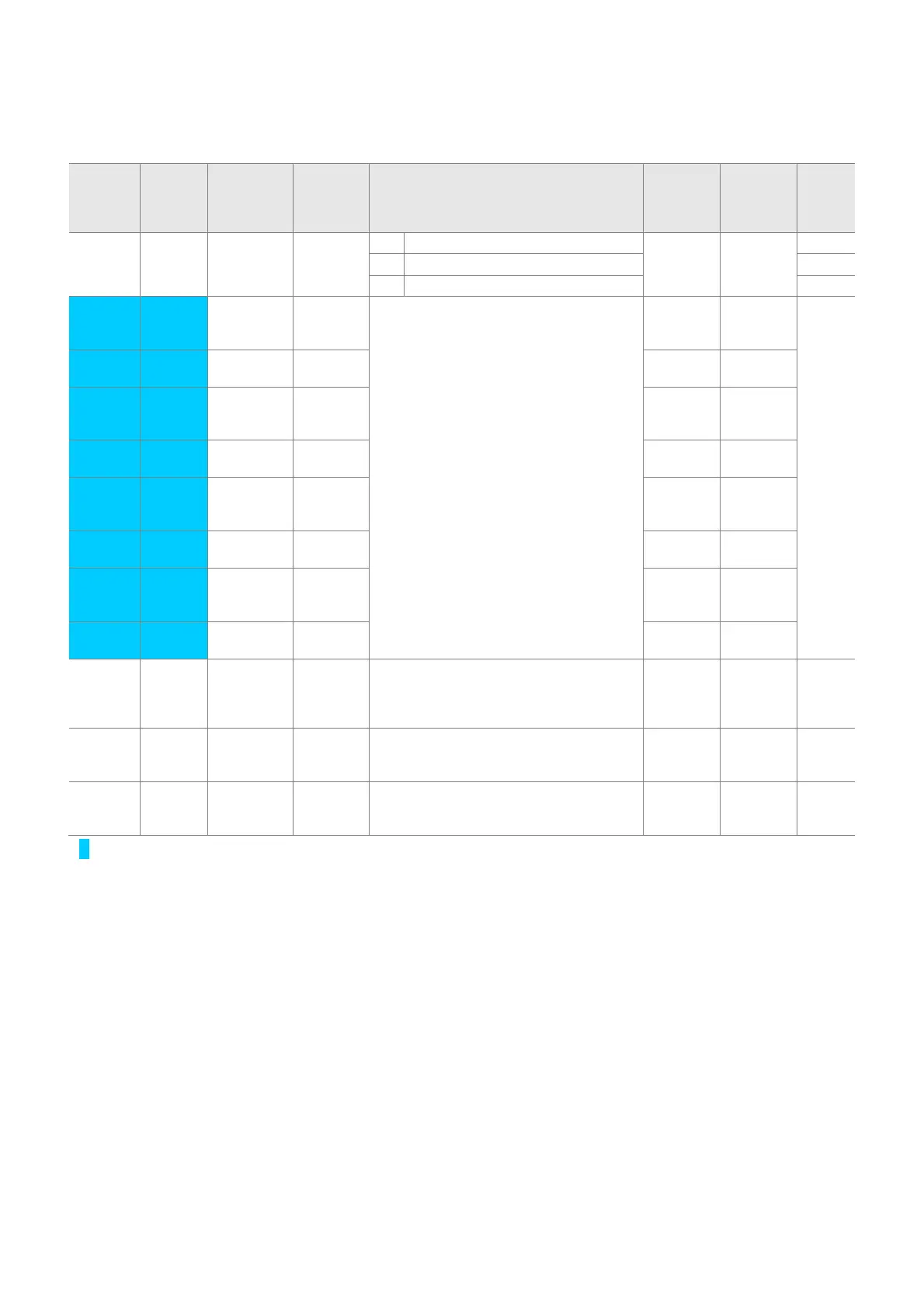
z Function group 1
LED
display
Address
for
commu
nication
Parameter
name
Min/Max
range
Description
Factory
defaults
Adj.
during
run
Page
F30 A21E [V/F
pattern]
0 ~ 2 0 {Linear} 0 X 7-17
1 {Square} 7-17
2 {User V/F} 7-18
F31
A21F [User V/F
frequency
1]
0 ~ 400
[Hz]
It is used only when V/F pattern is set to
2(User V/F)
It cannot be set above F21 – [Max
frequency].
The value of voltage is set in percent of
H70 – [Motor rated voltage].
The values of the lower-numbered
parameters cannot be set above those of
higher-numbered.
15.00 X 7-18
F32
A220 [User V/F
voltage 1]
0 ~ 100
[%]
25 X
F33
A221 [User V/F
frequency
2]
0 ~ 400
[Hz]
30.00 X
F34
A222 [User V/F
voltage 2]
0 ~ 100
[%]
50 X
F35
A223 [User V/F
frequency
3]
0 ~ 400
[Hz]
45.00 X
F36
A224 [User V/F
voltage 3]
0 ~ 100
[%]
75 X
F37
A225 [User V/F
frequency
4]
0 ~ 400
[Hz]
60.00 X
F38
A226 [User V/F
voltage 4]
0 ~ 100
[%]
100 X
F39 A227 [Output
voltage
adjustment
]
40 ~ 110
[%]
This parameter adjusts the amount of
output voltage.
The set value is the percentage of input
voltage.
100 X 7-18
F40 A228 [Energy-
saving
level]
0 ~ 30
[%]
This parameter decreases output voltage
according to load status.
0 0 8-17
F50 A232 [Electronic
thermal
select]
0 ~ 1
This parameter is activated when the
motor is overheated (time-inverse).
0 0 10-1
1)
: Set F30 to 2(User V/F) to display this parameter.

 Loading...

