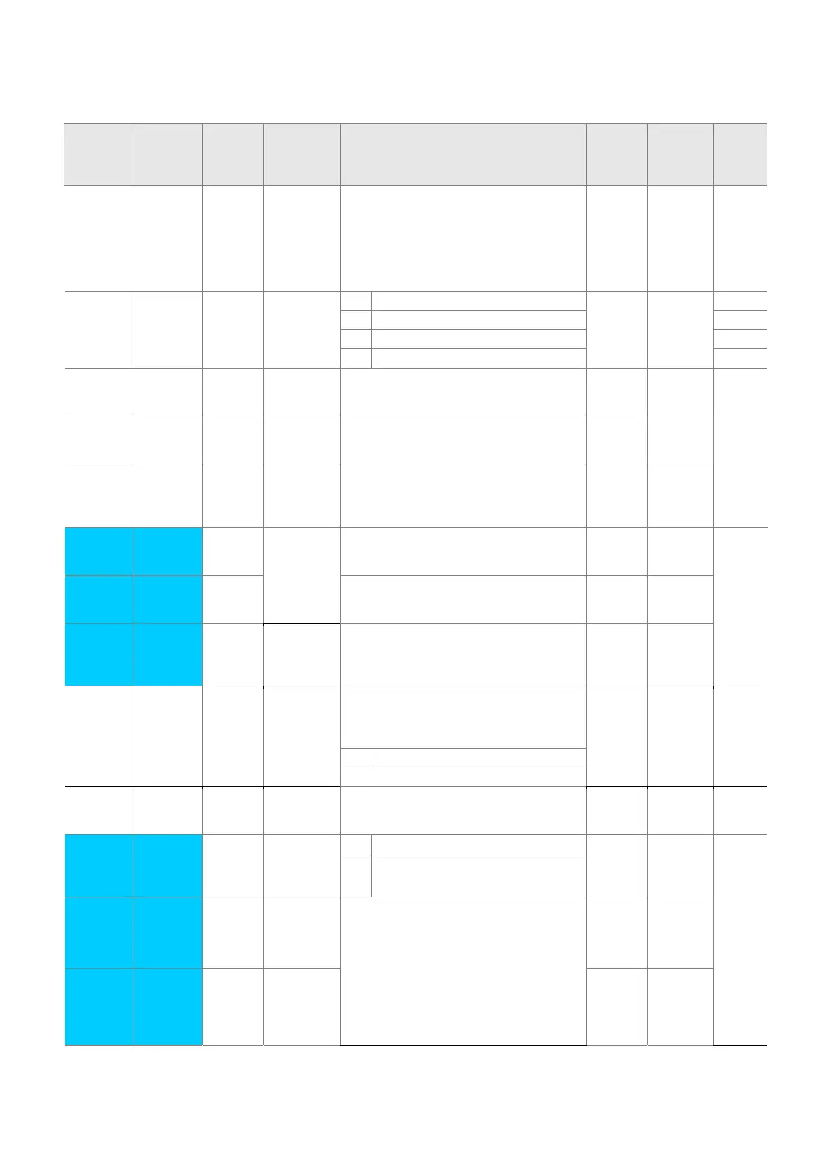
5-13
z Function group 2
LED
display
Address
for
communi
cation
Paramet
er name
Min/Max
range
Description
Factory
defaults
Adj.
during
run
Page
H39 A327 [Carrier
frequen
cy
select]
1 ~ 15
[kHz]
This parameter affects the audible sound
of the motor, noise emission from the
inverter, inverter temp, and leakage
current. If the set value is higher, the
inverter sound is quieter but the noise
from the inverter and leakage current will
become greater.
3 O 8-21
H40 A328 [Control
mode
select]
0 ~ 3 0 {Volts/frequency Control} 0 X 7-17
1 {Slip compensation control} 8-8
2 -
3 {Sensorless vector control} 8-15
H41 A329 [Auto
tuning]
0 ~ 1 If this parameter is set to 1, it
automatically measures parameters of
the H42 and H44.
0 X 8-14
H42 A32A [Stator
resistan
ce (Rs)]
0 ~ 28
[Ω]
This is the value of the motor stator
resistance.
- X
H44 A32C [Leakag
e
inductan
ce (Lσ)]
0~ 300.0
[mH]
This is leakage inductance of the stator
and rotor of the motor.
- X
H45
1)
A32D [Sensorl
ess P
gain]
0~ 32767 P gain for Sensorless control 1000 O
H46
A32E [Sensorl
ess I
gain]
I gain for Sensorless control 100 O
H47
A32F [Sensorl
ess
torque
limit]
100~220[
%]
Limits output torque in sensorless mode,. 180.0 X
H48
A330 PWM
mode
select
0~1 If you want to limit a inverter leakage
current, select 2 phase PWM mode.
It has more noise in comparison to
Normal PWM mode.
0 X 8-30
0 Normal PWM mode
1 2 phase PWM mode
H49
A331 PID
control
select
0~1 Selects whether using PID control or not 0 X 8-10
H50
2)
A332 [PID
Feedba
ck
select]
0 ~ 1 0 Terminal I input (0 ~ 20 mA) 0 X 8-10
1 Terminal V1 input (0 ~ 10 V)
H51
A333 [P gain
for PID
controlle
r]
0~ 999.9
[%]
This parameter sets the gains for the PID
controller.
300.0 O
H52
A334 [Integral
time for
PID
controlle
r
0.1~32.0
[sec]
1.0 O

 Loading...

