7-5
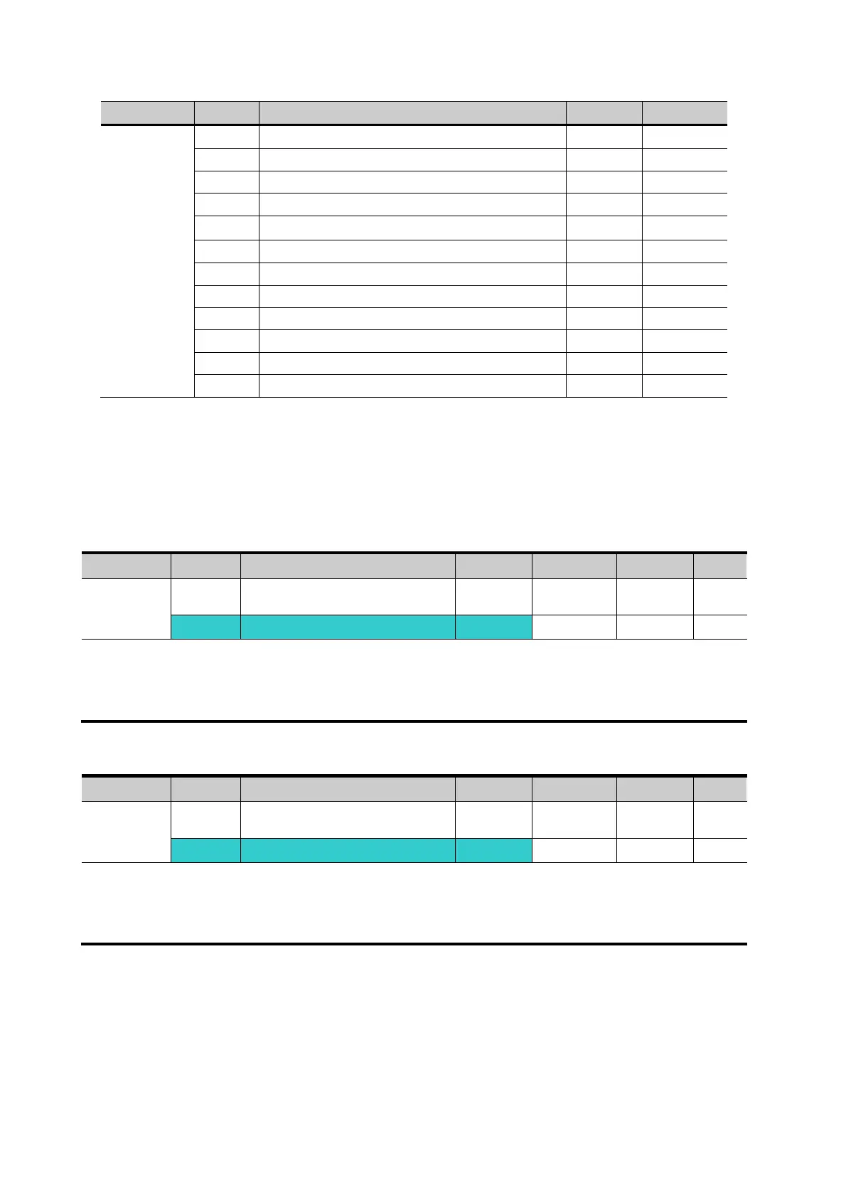
Group Code Parameter Name Setting Unit
I/O group I 2 [NV input Min voltage] 0 V
I 3 [Frequency corresponding to I 2] 0.00 Hz
I 4 [NV input Max voltage] 10.00 V
I 5 [Frequency corresponding to I 4] 5.00 Hz
I7
[V1 input Min voltage]
0 V
I 8
[Frequency corresponding to I 7]
0.00 Hz
I 9 [V1 input max voltage] 10 V
I10 [Frequency corresponding to I 9] 5.00 Hz
I12 [I input minimum current] 4 mA
I13 [Frequency corresponding to I 12] 0.00 Hz
I14 [I input max current] 20 mA
I15
[Frequency corresponding to I 14]
60.00 Hz
After the above setting is made, if 5V is applied to V1 with 12mA given to terminal I, output
frequency would be 32.5Hz. If –5V is applied to V1 terminal with 12mA given to terminal I, output
frequency would be 27.5Hz.
z Frequency setting via 0 ~ 10[V] + 0 ~ 20[mA] input
Group Code Parameter Name Setting Range Initial Unit
Drive
group
0.00 [Frequency Command] - 0 ~400 0.00 Hz
Frq [Frequency Mode] 6
0 ~ 8 0
Select 6 in Frq code of Drive group.
Related code: I 6 ~ I 10, I 11 ~ I 15
Refer to Frequency setting via -10 ~ +10V voltage input + 0 ~ 20mA input.
z Frequency setting via RS 485 communication
Group Code Parameter Name Setting Range Initial Unit
Drive
group
0.0 [Frequency Command] - 0 ~400 0.00 Hz
Frq [Frequency Mode] 7
0 ~ 8 0
Select 7 in Frq code of Drive group.
Related code: I 59, I 60, I 61
Refer to Chapter 13. RS485 communication.

 Loading...

