Chapter 4 RTD Input Module (XBF-RD04A, XBF-RD01A)
4.15.2 Operation parameter setting area
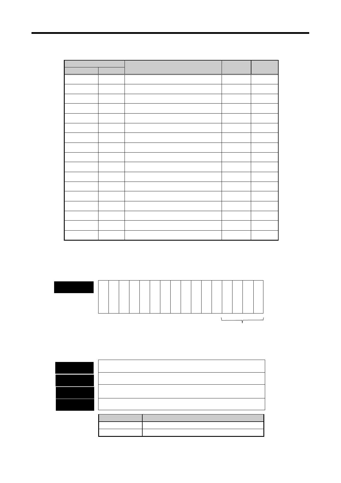
Operation parameter setting areas of RTD input module are as follows.
Details R/W Remark
0
H
0 Channel enable/disable setting R/W PUT
1
H
1 CH0 sensor type setting R/W PUT
2
H
2 CH1 sensor type setting R/W PUT
3
H
3 CH2 sensor type setting R/W PUT
4
H
4 CH3 sensor type setting R/W PUT
H
5 Temperature display unit setting R/W
H
6 CH0 filter constant setting R/W
H
7 CH1 filter constant setting R/W
H
8 CH2 filter constant setting R/W
H
9 CH3 filter constant setting R/W
H –
H
10~17 Not used
− −
H
18 Scaling setting R/W
H -
H
19~67 Not used
− −
H
68 CH0 disconnection information (code) R/W
H
69 CH1 disconnection information (code) R/W
70 CH2 disconnection information (code) R/W
71 CH3 disconnection information (code)
(1) Run channel setting
If Run channel is not specified, all channels will be stop status.
(2) Sensor type setting
If it is not specified manually, all channels will be specified as Pt100.
— — — — — — — — — — — —
C
H
3
C
H
2
C
H
1
C
H
0
bit15 bit14 bit13 bit12 bit11 bit10 bit9 bit8 bit7 bit6 bit5 bit4 bit3 bit2 bit1 bit0
Ch0 sensor type setting
Ch1 sensor type setting
Ch2 sensor type setting
Ch3 sensor type setting
Setting channel to use (bit)
Bit On (1): Run, Bit Off (0): Stop
4 - 23
 Loading...