Chapter 5 Thermocouple Input Module (XBF-TC04S,TC04B)
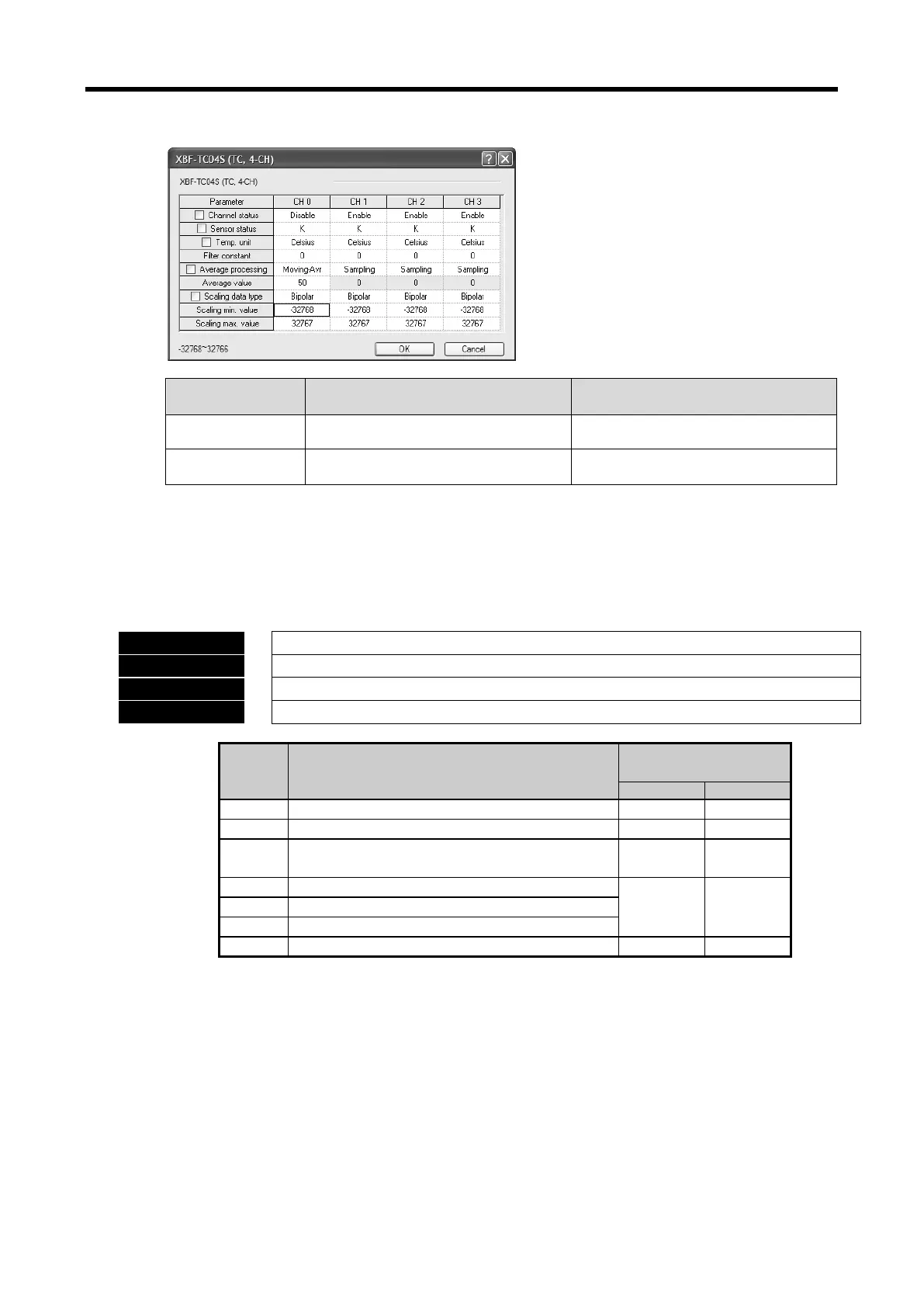
(e) This area shows the same results with Scaling min./max. value setting in I/O parameter setting
window.
Scaling min. value Scaling max. value
Signed -32768 ~ [Scaling max. value -1] [Scaling min. value+1] ~ 32767
Unsigned 0 ~ [Scaling max. value-1] [Scaling min. value+1] ~ 65535
(9) Setting error information area (address 27~30)
(a) If there is error when setting parameter (address 1~26), error information is displayed at
address 27~30 per channel.
(b) In case of GET instruction, setting error information address is as follows.
B15 B14 B13 B12 B11 B10 B9 B8 B7 B6 B5 B4 B3 B2 B1 B0
CH0 setting error information
CH1 setting error information
CH2 setting error information
CH3 setting error information
Bit Description
Sensor type (Off: normal, On: error)
Filter constant (Off: normal, On: error)
Bit2
Average processing method
(Off: normal, On: error)
0A
H
~0D
H
10~13
Time-average value (Off: normal, On: error)
0E
H
~11
H
14~17
Count-average value (Off: normal, On: error))
Moving-average value (Off: normal, On: error)
Scaling range (Off: normal, On: error)
(c) In case there is error, setting error representation flag (U0x.01.8 ~ U0x.01.B, in case of IEC
type, %UX0.x.24 ~ %UX0.x.27) will be on, it acts as default value.
If setting error representation flag (U0x.01.8 ~ U0x.01.B) is on, check error information 1B
H
~
1F
H
(27~30) area and solve the error.
5 - 49
 Loading...