XGB Analog edition manual
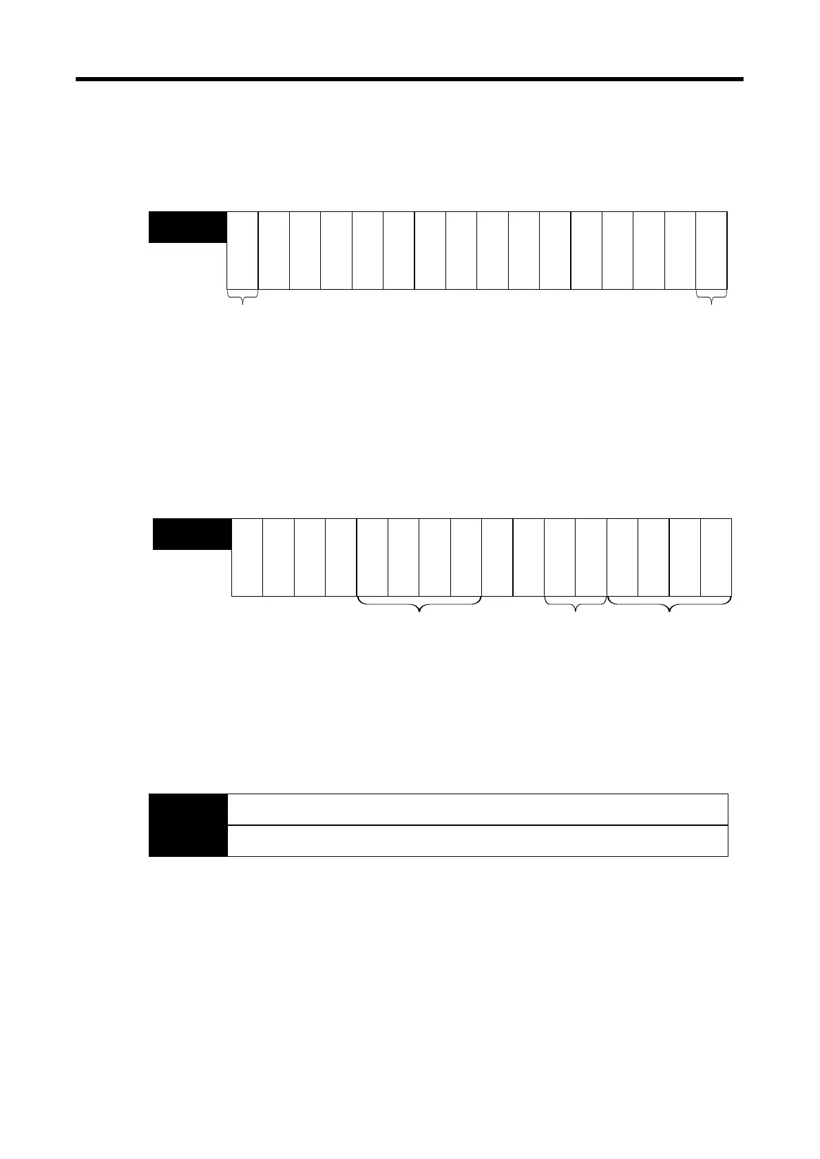
(1) Module Ready/Error Flag ( ( ) is for IEC types, x: slot No.)
(a) U0x.00.F(%UX0.x.15): at power on or reset of PLC CPU, turns on when the analog I/O
conversion is ready and analog conversion is performed.
(b) U0x.00.0(%UX0.x.0): the flag indicating the error status of A/D conversion module.
bit15
bit14
bit13
bit12
bit11
bit10
bit9
bit8
bit7
bit6
bit5
bit4
bit3
bit2
bit1
bit0
--
-
-
-
-
-
-
-
-
-
U0x.00
(%UW0.x.0)
Error occurrence
information
Bit On (1): error
Bit Off (0): Normal
Ready
Error
-
- -
Module READY
Bit On (1): Normal
Bit Off (0): error
(2) Operation channel information/ open-wire detection information/ channel error information flags
( ‘( )’ is for IEC types, x: slot No.)
This is the area for storing the operation information, input wire open detection and channel error
information by channel.
※ The base No. of the XGB PLC is 0.
Bit15 Bit14
Bit13
Bit12
Bit11
Bit10
Bit9 Bit8
Bit7
Bit6 Bit5
Bit4 Bit3
Bit2
Bit1
Bit0
O
u
t
p
u
t
C
H
.
1
O
u
t
p
u
t
C
H
.
0
I
n
p
u
t
C
H
.
1
I
n
p
u
t
C
H
.
0
--
---
-
U0x.01
(%UW0.x.1)
Operation Ch, Info.
Bit On (1): in operation
Bit Off (0): Stop operation
I
n
p
u
t
C
H
.
1
I
n
p
u
t
C
H
.
0
O
u
t
p
u
t
C
H
.
1
O
u
t
p
u
t
C
H
.
0
I
n
p
u
t
C
H
.
1
I
n
p
u
t
C
H
.
0
Open-wire detection info.
Bit On (1): open-wire
Bit Off (0): normal
Channel Error Info.
Bit On (1): error
Bit Off (0): normal
(3) Digital Output Values ( ( ) is for IEC types, x: slot No.)
(a) A/D converted digital values are outputted to buffer memory address U0x.04 ~ U0x.05
(%UW0.x.4 ~ %UW0.x.5) by channel-basis.
(b) Digital output values are saved in 16-bit binary figures.
※ The base No. of the XGB PLC is 0.
Bit15
Bit14 Bit13 Bit12 Bit11
Bit10
Bit9 Bit8
Bit7 Bit6 Bit5 Bit4
Bit3
Bit2 Bit1
Bit0
Input channel 0 converted value
U0x.04
(%UW0.x.4)
Input channel 1 converted value
U0x.05
(%UW0.x.5)
6 - 34
 Loading...