Chap. 6 Analog I/O Module (XBF-AH04A)
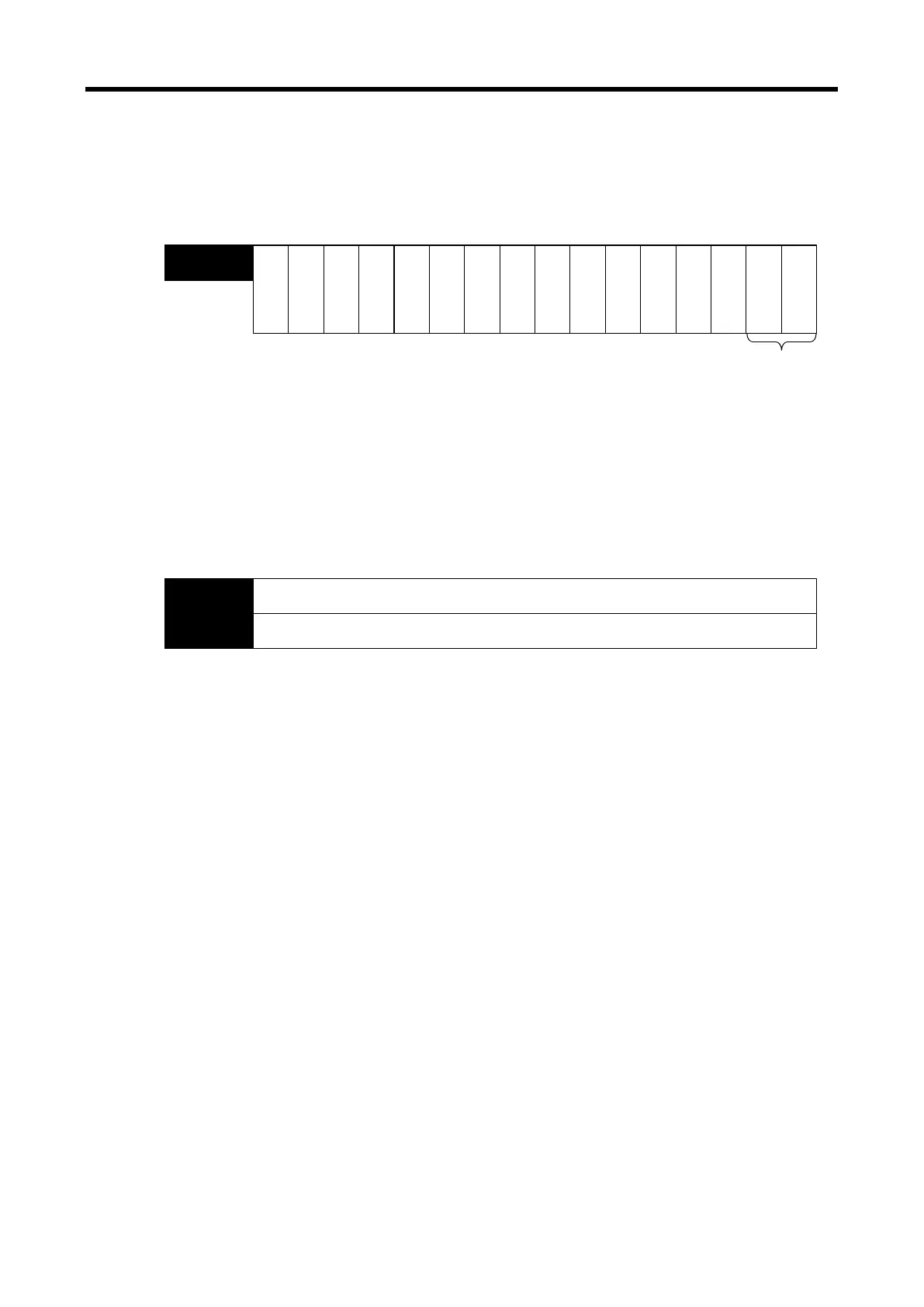
(4) Output Permit Setting ( ( ) is for IEC types, x: slot No.)
(a) Output permit/prohibit can be set up for each channel.
(b) The default setting is ‘Output Prohibited.’
※ The base No. of the XGB PLC is 0.
Bit15
Bit14
Bit13
Bit12
Bit11 Bit10 Bit9 Bit8 Bit7 Bit6 Bit5 Bit4 Bit3 Bit2 Bit1
Bit0
O
u
t
p
u
t
C
H
.
1
O
u
t
p
u
t
C
H
.
0
------
U0x.06
(%UW0.x.6)
Output status setting
BitOn (1): Output permitted
BitOff (0): Output prohibited
---
- ----
(5) Digital Input Values ( ( ) is for IEC types, x: slot No.)
(a) Digital inputs can be set up as unsigned (-48~4047), signed (-2048~2047), precision, or
percentile (-12~1011) values.
(b) When digital input value is not set up, they are processed as zero.
※ The base No. of the XGB PLC is 0.
Bit15 Bit14
Bit13
Bit12 Bit11
Bit10 Bit9
Bit8
Bit7 Bit6 Bit5 Bit4 Bit3
Bit2 Bit1
Bit0
Output channel 0 input value
U0x.07
(%UW0.x.7)
Output channel 1 input value
U0x.08
(%UW0.x.8)
6 - 35
 Loading...