Chap. 6 Analog I/O Module (XBF-AH04A)
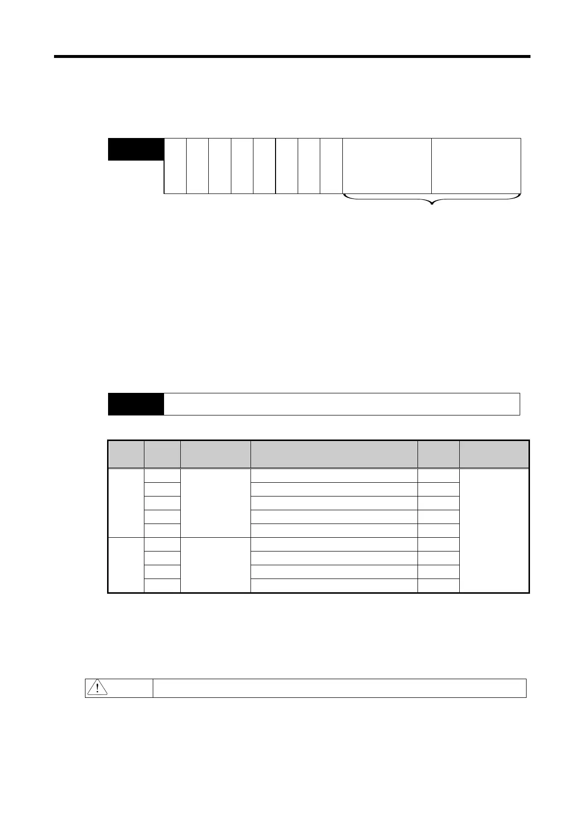
(7) Output Status Setting
(a) This sets up the analog output status when the XGB base unit is changed from run to stop.
(b) Default setting is the Previous Value output.
Bit15 Bit14 Bit13 Bit12 Bit11 Bit10 Bit9 Bit8 Bit7 Bit6 Bit5 Bit4
Bit3
Bit2 Bit1 Bit0
Output Ch.0
Address8
Output Ch.1
Output channel status setting (4 bit per Ch)
0 : Previous value output
1 : Min. value output
2 : Median value output
3 : Max. value output
---- ----
(8) Error Code (Address 9)
(a) Saves the error code detected by the analog I/O module.
(b) The types and descriptions of the error are as follows.
Bit15
Bit14
Bit13
Bit12
Bit11
Bit10
Bit9
Bit8
Bit7
Bit6
Bit5
Bit4
Bit3
Bit2
Bit1
Bit0
Set-up error information
Address9
Type
Error
Code
LED Lamp Description
Priority
Order
Remark
Input
Error
INPUT LED
flickering 1s
intervals
Input Ch range setting error
#: Ch No.
Input Ch. 0,1
Output Ch. 0,1
20# Input Ch data type setting error 3
30# Input Ch filter cons. Setting error 4
40# Input Ch averaging setting error 5
50# Input Ch average value setting error 6
Output
Error
60#
OUTPUT LED
flickering 1s
intervals
Output Ch range setting error 7
Output Ch data type setting error
80# Output Ch status setting error 9
90# Output Ch input value range-over error 1
(c) In case of plural errors, the code with higher priority order will be saved.
(9) System Area (after Address 10)
(a) System area (after address 10) is read/write protected.
Modifying this area can cause malfunction of failure of product.
6 - 39