Chapter 7 Analog Input Module (XBF-AD08A)
- In the device allocation, the small letter ‘y’ is the No. of the slot where the module is installed.
- For example, to read the ‘CH3 Output’ of the analog module installed in the slot 4, write in U04.05.
(%UW0.4.5 for IEC types)
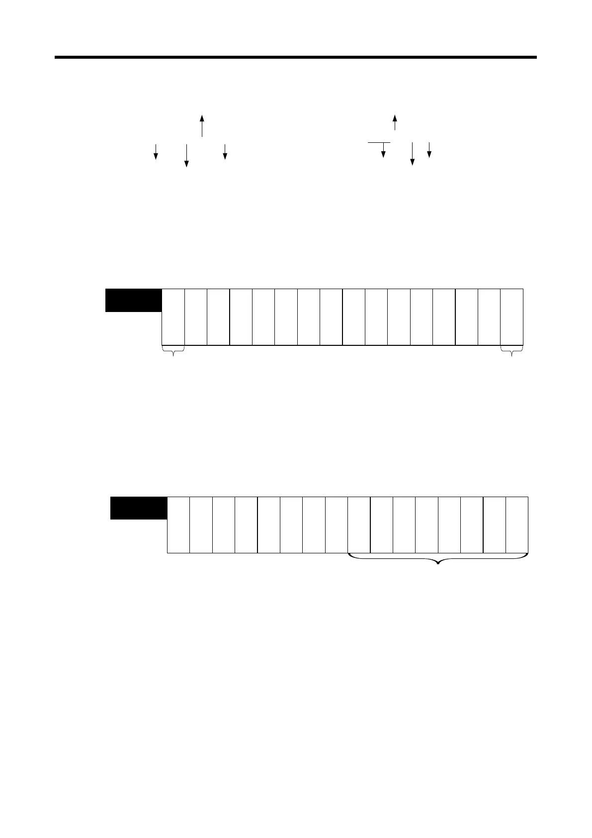
Device Type
U 0 4 . 0 5
Slot No.
Word
[“S”or“H”type]
Word classifier
Device Type
Slot No.
Base No
Word
[IEC type]
% U W 0 . 4 . 5
(1) Module Ready/Error Flag ( ( ) is for IEC types, y: slot No.)
(a) U0y.00.F (%UX0.y.15): at power on or reset of PLC CPU, turns on when the analog I/O
conversion is ready, and analog conversion is performed.
(b) U0y.00.0(%UX0.y.0): the flag indicating the error status of A/D conversion module.
bit15 bit14 bit13 bit12 bit11 bit10 bit9 bit8 bit7
bit6 bit5 bit
4 bit3 bit2 bit1 bit0
-----------
U0x.00
(%UW0.x.0)
Error occurrence
information
Bit On (1): error
Bit Off
(0): Normal
Ready
Error
-
- -
Module READY
Bit On (1): Normal
Bit Off
(0): error
(2) Operation channel information
( ( ) is for IEC types, x: slot No.)
This is the area for storing the operation information, input wire open detection,
and channel error information by channel.
※ The base No. of the XGB PLC is 0.
Bit15 Bit14 Bit13 Bit12 Bit11 Bit10 Bit9 Bit8 Bit7 Bit6 Bit5 Bit4 Bit3 Bit2 Bit1 Bit0
C
H
.
3
C
H
.
2
C
H
.
1
C
H
.
0
C
H
.
6
C
H
.
7
----
U0x.01
(%UW0.x.1)
Operation Ch, Info.
Bit On (1): in operation
Bit Off (0): Stop operation
C
H
.
5
C
H
.
4
- - - -
7 - 29
 Loading...