Chapter 7 Analog Input Module (XBF-AD08A)
7.11.2 Operation Parameter Setting Area
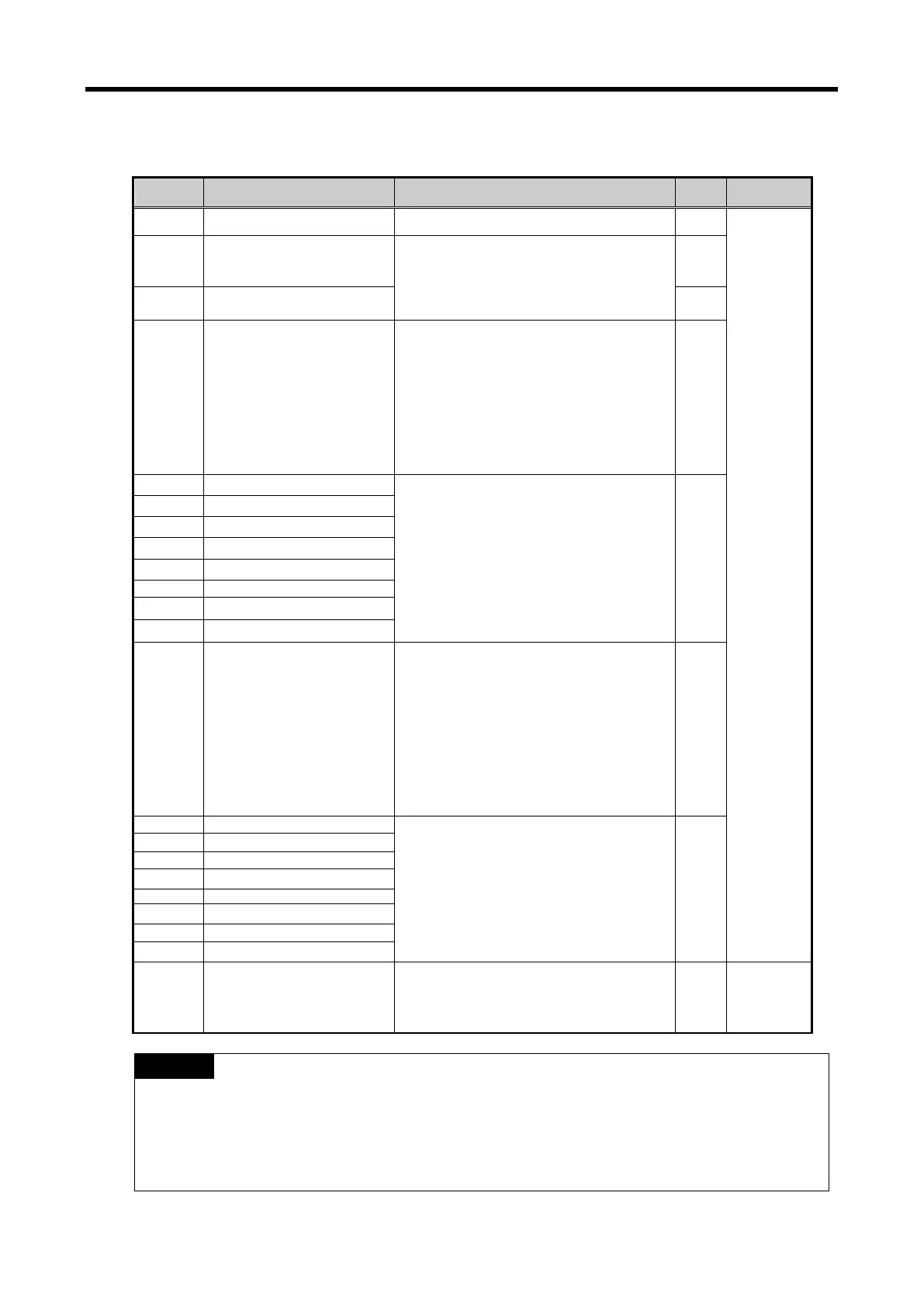
The operation parameter setting area of the analog mix module is as follows.
Description Setting R/W Command
0 Appoint operating channel Bit Off (0): stop, Bit ON (1): run R/W
PUT/GET
1
I/O range setting
(CH0~CH3)
0000: 4 ~ 20 ㎃
0001: 0 ~ 20 ㎃
0010: 1 ~ 5 V
0011: 0 ~ 5 V
R/W
2
I/O range setting
(CH4~CH7)
R/W
3 Output data type setting
Input data type setting (bit)
00: 0 ~ 4000
01: -2000 ~ 2000
10: precise value
11: 0 ~ 1000
- In case of precise value
4 ~ 20 ㎃: 400 ~ 2000
0 ~ 20 ㎃: 0 ~ 2000
1 ~ 5 V: 100 ~ 500
0 ~ 5 V: 0 ~ 500
R/W
0 or 4 ~ 64000 R/W
11 CH7 Filter constant
12 Average processing method
Specifies average processing method (2bit
per channel)
00: Sampling processing
01: Time average processing
10: Count average processing
11: Moving average processing
R/W
Time average: 4 ~ 16000 [ms]
Count average: 2 ~ 64000 [times]
Moving average: 2 ~ 100
R/W
21 Error information
Error information (Decimal, # channel n0.)
0-7: CH0-7
10#: error in channel range
20#: error in channel filter value
30#: error in channel average value
R GET
(1) If the memory address 0~8 area is entered with values different from the setting
U0x.01.8~U0x.01.B (setting error representative flag, for IEC type, %UX0.x.24~%UX0.x.27) is
ON and runs with default values. The error information is displayed in the setting error
information are (No. 9).
(2) System areas (after No. 10) are read/write protected.
Changing these areas may cause malfunction or failure of the product.
7 - 31
 Loading...