XGB Analog edition manual
(4) Channel output state setting area (address 8)
(a) Set the output state setting with the following code
(b) If you set more than 4, 0 (former value) will be set forcibly.
But, U0X.01.A~ U0X.01.B (Setup error flag) will be ON.
(c) When using PUT instruction, address is as follows
Bit15
Bit14
Bit13
Bit12 Bit11 Bit10
Bit9
Bit8
Bit7
Bit6
Bit5
Bit4
Bit3 Bit2
Bit1
Bit0
Output CH 0
8
Input data type (4bit per channel)
0 : Former value
1 : Min value
2 : Middle value
3 : Max value
Output CH 1---- -
--
-
(d) The values set in bit 8~15 are ignored.
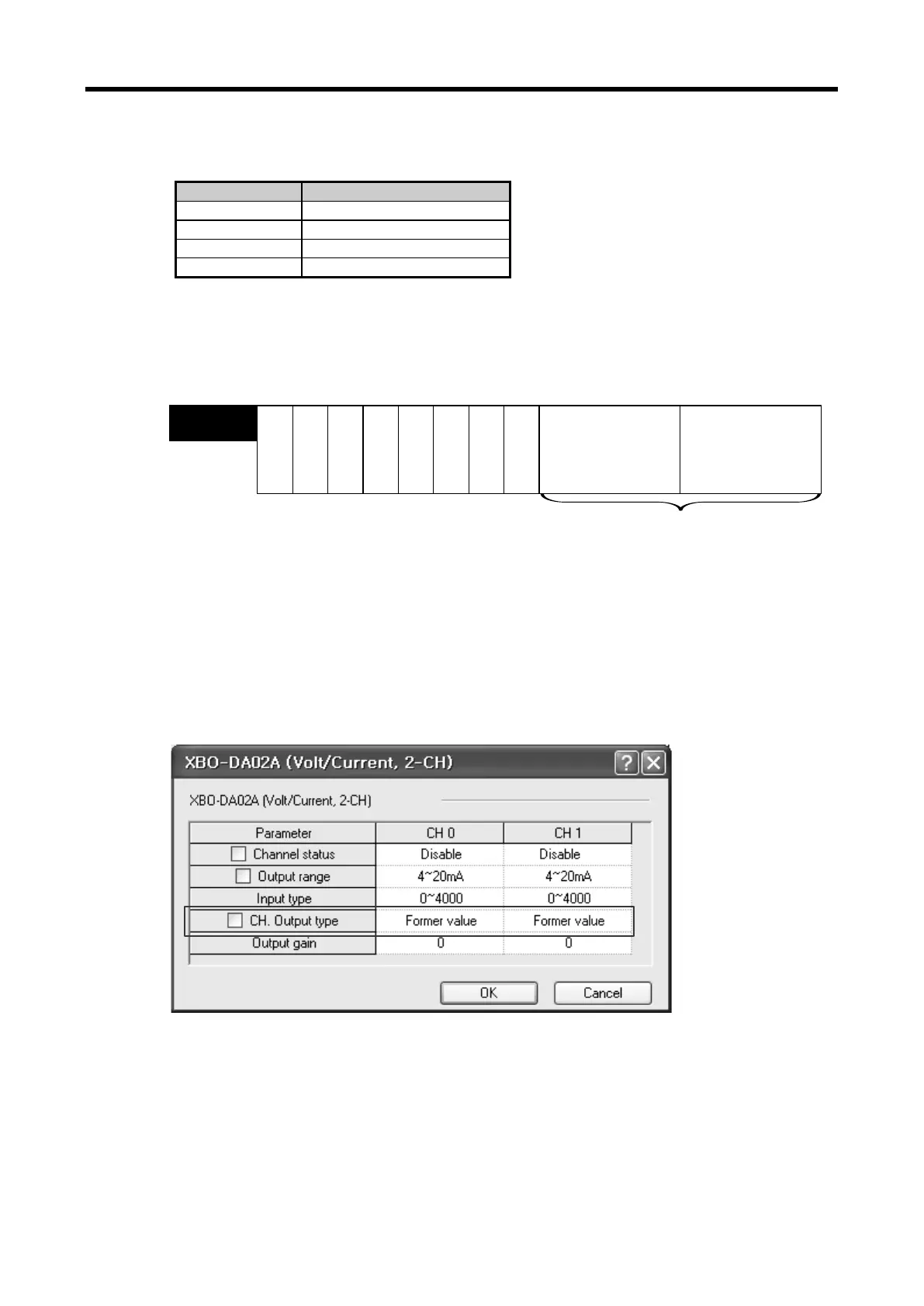
(e)This area is same as setting in “CH. Output type” of I/O parameter
9 - 28
 Loading...