XGB Analog edition manual
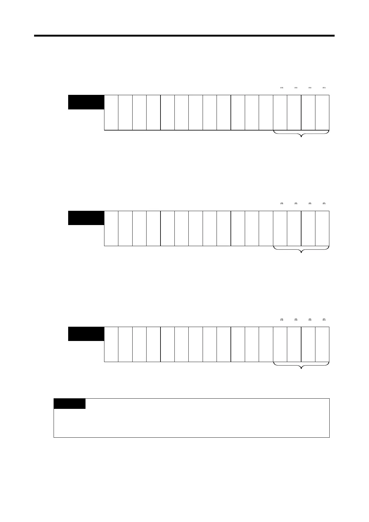
4) Input disconnection flag (( ) means the case of IEC type, y: slot number)
The area where the input disconnection detection signal of each channel is saved.
U0y.10.0 ~ U0y.10.3 (%UX0.y.160 ~ %UX0.y.163)
※ XGB PLC’s base number is 0.
C
h
a
n
n
e
l
3
C
h
a
n
n
e
l
2
C
h
a
n
n
e
l
1
C
h
a
n
n
e
l
0
--
--
U0y.10
(%UW0.y.10)
Input disconnection detection
Bit On (1): occurrence of input disconnection
Bit Off (0): Normal
---- -
-
--
Bit 15 Bit 14 Bit 13 Bit 12 Bit 11 Bit 10 Bit 9 Bit 8
Bit 7
Bit 6
Bit 5
Bit 4 Bit 3
Bit 2
Bit 1
Bit 0
5) High limit alarm flag (( ) means the case of IEC type, y: slot number)
The area where the high limit alarm detection signal of each channel is saved.
U0y.11.0 ~ U0y.11.3 (%UX0.y.176 ~ %UX0.y.179)
※ XGB PLC’s base number is 0.
C
h
a
n
n
e
l
3
C
h
a
n
n
e
l
2
C
h
a
n
n
e
l
1
C
h
a
n
n
e
l
0
-
--
-
U0y.011
(%UW0.y.11)
Maximum warning detection
Bit On (1): occurrence of maximum warning
Bit Off (0): Normal
---- -
---
Bit 15 Bit 14 Bit 13
Bit 12
Bit 11 Bit 10
Bit 9
Bit 8 Bit 7 Bit 6
Bit 5 Bit 4
Bit 3 Bit 2
Bit 1
Bit 0Bit 15
Bit 14 Bit 13
Bit 12
Bit 11 Bit 10
Bit 9
Bit 8 Bit 7 Bit 6
6) Low limit alarm flag (( ) means the case of IEC type, y: slot number)
The area where the low limit alarm detection signal of each channel is saved.
U0y.12.0 ~ U0y.12.3 (%UX0.y.192 ~ %UX0.y.195)
※ XGB PLC’s base number is 0.
C
h
a
n
n
e
l
3
C
h
a
n
n
e
l
2
C
h
a
n
n
e
l
1
C
h
a
n
n
e
l
0
----
U0y.12
(%UW0.y.12)
---- ----
Bit 5 Bit 4 Bit 3 Bit 2 Bit 1 Bit 0Bit 15 Bit 14 Bit 13 Bit 12 Bit 11 Bit 10 Bit 9 Bit 8 Bit 7 Bit 6
Minimum warning detection
Bit On (1): occurrence of minimum warning
Bit Off (0): Normal
(1) If the external 24V power is not provided, operating channel information [U0y.01.0~U0y.01.3
(%UX0.y.16 ~%UX0.y.19)], input disconnection flag [U0y.10.0~U0y.10.3(%UX0.y.160~
%UX0.y.163)], high limit alarm flag [U0y.11.0~U0y.11.3(%UX0.y.176~%UX0.y.179)], low limit
alarm flag [U0y.12.0~U0y.12.3 (%UX0.y.192 ~ %UX0.y.195)] will be off.
13 - 38
 Loading...