Chapter 13 Analog Input Module (XBF-AD04C)
13.11.2 Operation parameters setting area
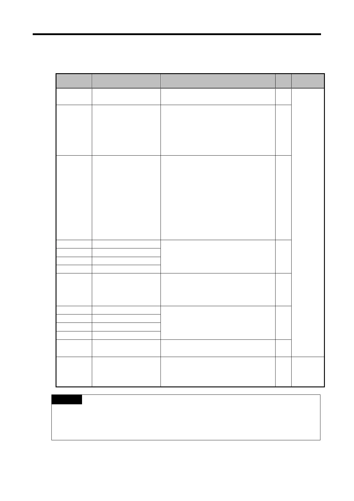
Setting area of A/D conversion module’s Run parameters is as described in Table.
Descriptions Details R/W
Remark
0 Specify channel to use
Bit 0 ~ Bit 3
0: Stop, 1: Run
R/W
PUT/GET
1
Specify range of input
voltage/current
Input range setting (4 Bits)
0000 : 4 ~ 20㎃
0001 : 0 ~ 20㎃
0010 : 1 ~ 5 V
0011 : 0 ~ 5 V
0100 : 0 ~ 10 V
R/W
3
Specify range of output
data
Output data format setting (2 Bit)
00: 0 ~ 16,000
01: -8,000 ~ 8,000
10: Precise value
11: 0 ~ 10,000
- In case of precise value
4 ~ 20㎃: 4,000 ~ 20,000
0 ~ 20㎃
: 0 ~ 20,000
1 ~ 5V: 1,000 ~ 5,000
0 ~ 5V: 0 ~ 5,000
0 ~ 10V: 0 ~ 10,000
-10 ~ 10V: -10,000 ~ 10,000
R/W
0 or 4 ~ 64,000 R/W
12
Specify average
processing method
Average process (2 Bits)
00 : Sampling process
01 : Time average process
10 : Number of average process
R/W
Input channe average type setting
Time average : 4 ~ 16,000 [ms]
Count average : 2 ~ 64,000 [times]
R/W
21 Hold last value
Bit 0 ~ Bit 3
0: Disable, 1: Enable
R/W
22 Setting error
0-3: CH 0-3 (10Dec, #: Channel No.)
10#: Channel range over
20#: Filter constant range over
30#: Average constant range over
R/W
GET
Notes
(1) When memory addresses of 1, 4~7, 13~16 areas are entered from external setting values,
U0y.01.8~U0y.01.B (representative flag of setting error, in case of IEC type) is on and operates
with basic setting value. Error information is shown on error information area(No. 22).
(2) The system area (after No. 23 ) is prohibited for reading/writing. If this area is changed,
malfunction and breakdown can be made.
13 - 39
 Loading...