Chapter14 Analog Output Module (XBF-DV04C/XBF-DC04C)
- In the device assigned, 'y' means slot number equipped with module.
- In order to read ‘CH2 conversion value’ of A/D conversion module installed on Slot No.4, it
shall be displayed as U04.05. (In case of IEC type %UW0.4.5)
Device Type
U 0 4 . 0 5
Slot No.
Word
[XBC type]
Word Separator
Device Type
Slot No.
Base No
Word
[IEC type]
% U W 0 . 4 . 5
- In order to read ‘CH1 conversion value’ of A/D conversion module installed on Slot No.5, it
shall be displayed as U05.02.1 (In case of IEC type %UW0.5.33)
Device Type
U 0 5 . 0 2
Slot No.
Word Separator
Word
. 1
Bit Separator
[XBC type]
Bit 1
Device Type
% U X 0 . 5 . 33
Slot No.
Base No
[IEC type]
Bit 33
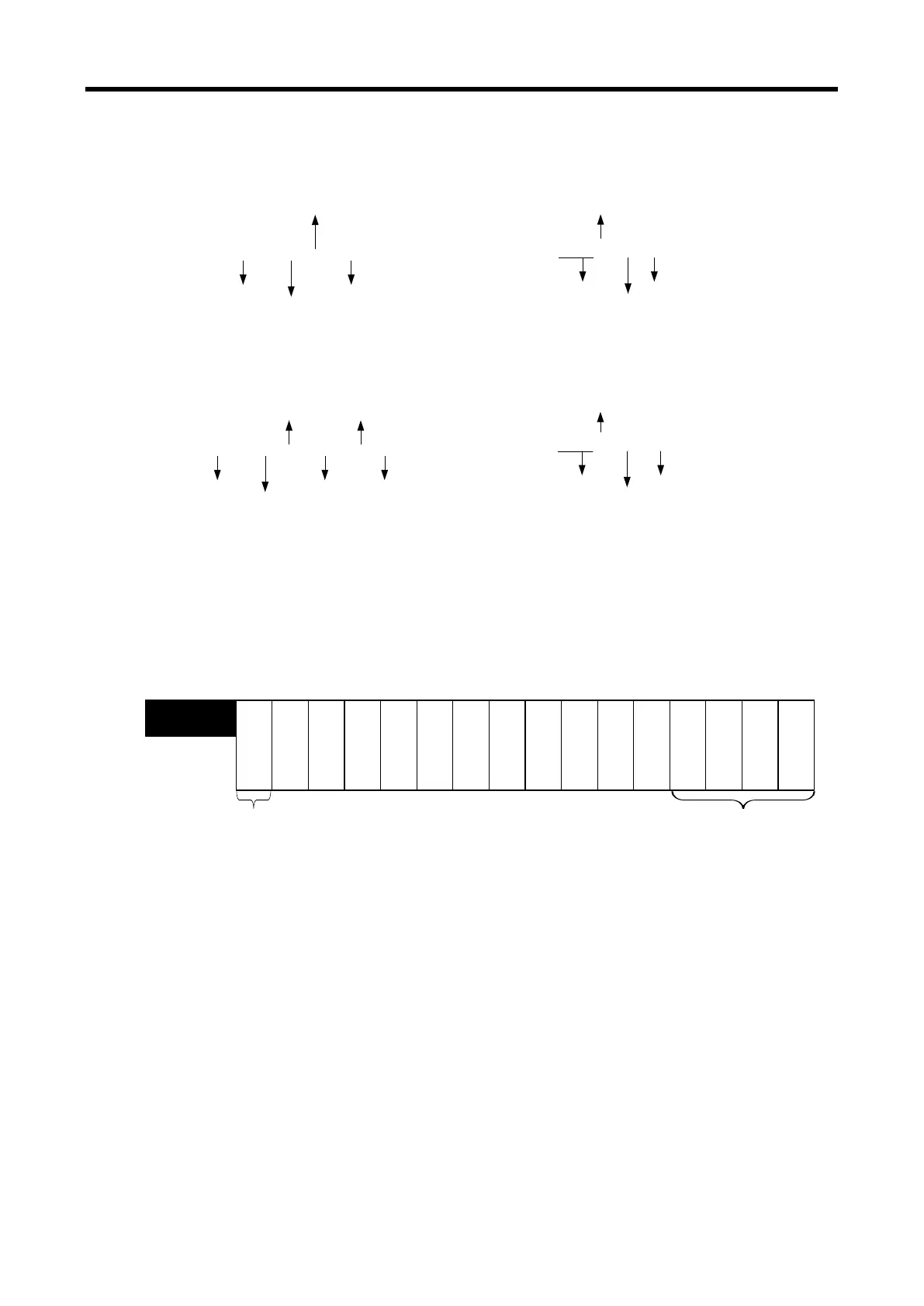
1) Module Ready/Error flag ( ‘( )’ means the case of IEC type, y: slot number)
(1) U0y.00.F(%UX0.y.15): It will be ON when PLC CPU is powered or reset with D/A
conversion ready to process A/D conversion.
(2) U0y.00.0 ~ U0y.00.3(%UX0.y.0 ~ %UX0.y.3): It is a flag to display the error status of D/A
conversion module.
※ The base number of XGB PLC is ‘0’.
Error information
Bit On (1): Error
Bit Off (0): Normal
Moudule READY
Bit On (1): Normal
Bit Off (0): Error
Bit 15 Bit 14 Bit 13 Bit 12 Bit 11
Bit 10
Bit 9 Bit 8 Bit 7 Bit 6 Bit 5 Bit 4
Bit 3
Bit 2 Bit 1 Bit 0
---
---
---
--
U0y.00
(%UW0.y.0)
Ready
Channel 0
C
h
a
n
n
e
l
3
C
h
a
n
n
e
l
2
C
h
a
n
n
e
l
1
14 - 29
 Loading...