XGB Analog edition manual
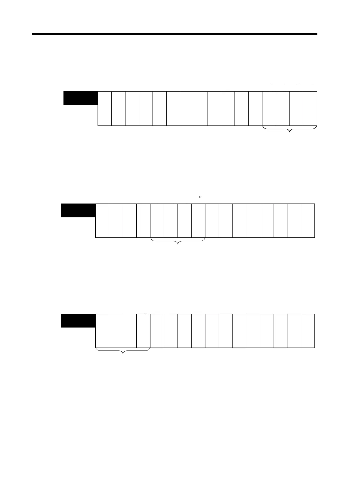
2) Channel operation information
(1) This area shows the channel being used.
※ The base number of XGB PLC is ‘0’.
C
h
a
n
n
e
l
3
C
h
a
n
n
e
l
2
C
h
a
n
n
e
l
1
C
h
a
n
n
e
l
0
-
-
--
-
-
U0y.01
(%UW0.y.1)
Channel information
Bit On (1): In operation
Bit Off (0): Stop
-
-
- -
-
-
Bit 15
Bit 14
Bit 13
Bit 12
Bit 11
Bit 10 Bit 9 Bit 8 Bit 7 Bit 6 Bit 5 Bit 4 Bit 3 Bit 2
Bit 1
Bit 0
3) Status of interpolation output
(1) This area shows the channel being outputting interpolation.
※ The base number of XGB PLC is ‘0’.
비트15
비트14 비트13
비트12 비트11 비트10 비트9
비트8
비트7
비트6
비트5 비트4 비트3
비트2
비트1 비트0
-
---
U0y.01
(%UW0.y.1)
C
h
a
n
n
e
l
2
C
h
a
n
n
e
l
3
C
h
a
n
n
e
l
1
C
h
a
n
n
e
l
0
---- ----
Bit 15 Bit 14 Bit 13 Bit 12 Bit 11
Bit 10
Bit 9 Bit 8
Bit 7
Bit 6
Bit 5
Bit 4
Bit 3
Bit 2 Bit 1 Bit 0
Interpolation output condition
Bit On (1): Interpolation output
Bit Off (0): Off
4) Output disconnection detection (Only for current output module XBF-DC04C)
(1) This area shows the channel detecting output disconnection.
※ The base number of XGB PLC is ‘0’.
C
h
a
n
n
e
l
0
C
h
a
n
n
e
l
1
C
h
a
n
n
e
l
2
C
h
a
n
n
e
l
3
U0y.01
(%UW0.y.1)
---- ----
----
Bit 15
Bit 14 Bit 13 Bit 12 Bit 11
Bit 10
Bit 9
Bit 8 Bit 7
Bit 6 Bit 5 Bit 4
Bit 3
Bit 2
Bit 1
Bit 0
Disconnection detection information
Bit On (1): occurrence of disconnection
Bit Off (0): Normal
14 - 30
 Loading...