Chapter14 Analog Output Module (XBF-DV04C/XBF-DC04C)
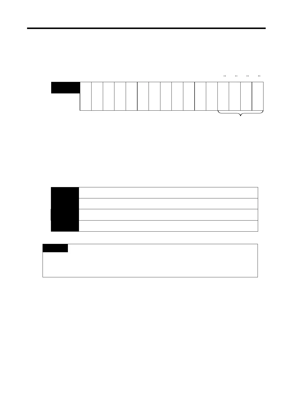
5) Output permission setting
(1) The output enable / disable for each channel can be set.
(2) When the output permission is not set, the output of all channels will be prohibited.
※ The base number of XGB PLC is ‘0’.
C
h
a
n
n
e
l
3
C
h
a
n
n
e
l
2
C
h
a
n
n
e
l
1
C
h
a
n
n
e
l
0
------
U0y.02
(%UW0.y.2)
Output permission information
Bit On (1): Permission
Bit Off (0): Prohibition
-
-
- -
- -
Bit 15 Bit 14 Bit 13
Bit 12 Bit 11 Bit 10 Bit 9 Bit 8 Bit 7 Bit 6 Bit 5 Bit 4 Bit 3 Bit 2 Bit 1 Bit 0
6) Digital input value
(1) Unsigned value(-192~16,191 / 0~16,191), Signed value(-8,192~8,191 / -8,000~8,191),
Precise value(-952~5,047 / -60~5,059 / -120~10,119 / -10,240~10,239 / 3,808~20,191 /
0~20,239), Percentile value(-120~10,119 / 0~10,119) can be used within these ranges
depending on the setting of input data type.
(2) If the digital input value is not set, it will be handled as '0'.
※ The base number of XGB PLC is ‘0’.
Channel 0 Digital input data
U0y.03
(%UW0.y.3)
Channel 1 Digital input data
U0y.04
(%UW0.y.4)
Channel 2 Digital input data
U0y.05
(%UW0.x.5)
Channel 3 Digital input data
U0y.06
(%UW0.y.6)
Bit 15 Bit 14
Bit 13
Bit 12 Bit 11
Bit 10
Bit 9 Bit 8
Bit 7 Bit 6
Bit 5
Bit 4
Bit 3
Bit 2 Bit 1
Bit 0
Notes
(1) If the external 24V is not supplied, the operation channel information [U0y.01.0 ~
U0y.01.3, (%UX0.y.16 ~ %UX0.y.19)], interpolation output status flag [U0y.01.8 ~
U0y.01.B (%
UX0.y.24 ~ %UX0.y.27)], output disconnection detection flag [U0y.01.C
~ U0y.01.F (%UX0.y.28 ~ %UX0.y.31) ], will be turned off.
14 - 31
 Loading...