XGB Analog edition manual
14.11.2 Operation parameters setting area
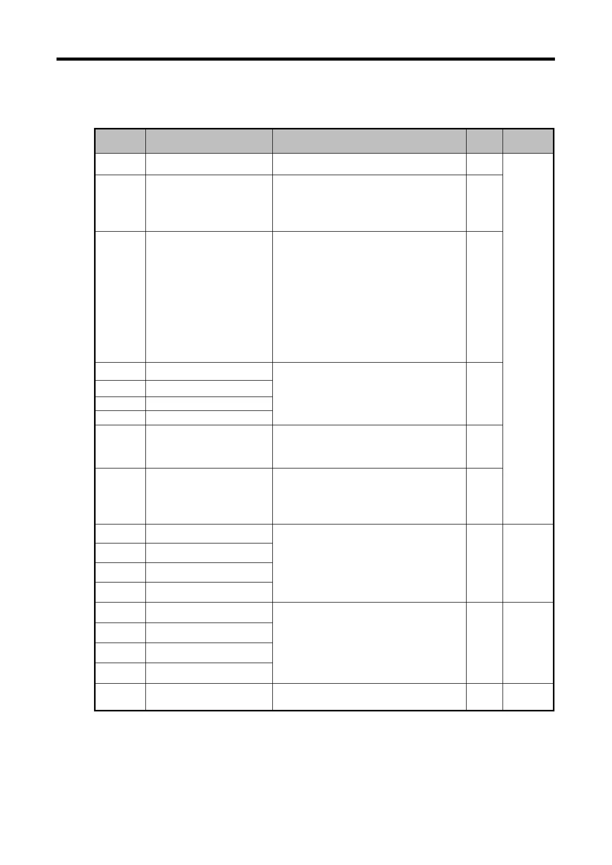
Setting area of D/A conversion module’s Run parameters is as described in Table.
Descriptions Details R/W Remark
0 Specify channel to use
Bit 0 ~ Bit 3
0: Stop, 1: Operation
R/W
PUT/GET
1 Specify voltage output range
Output range setting (2Bit)
00 : 1 ~ 5 V (4 ~ 20㎃)
01 : 0 ~ 5 V (0 ~ 20㎃)
10 : 0 ~ 10 V
R/W
2
Specify input type
Input data type setting (2Bit)
00: 0 ~ 16,000
01: -8,000 ~ 8,000
10: Precise value
11: 0 ~ 10,000
- In case of precise value
4 ~ 20㎃: 4,000 ~ 20,000
0 ~ 20㎃
: 0 ~ 20,000
1 ~ 5V: 1000 ~ 5,000
0 ~ 5V: 0 ~ 5,000
0 ~ 10V: 0 ~ 10,000
-10 ~ 10V: -10,000 ~ 10,000
R/W
3 Specify Ch0 output setting
Output status setting (2Bit)
00: Previous value output
01: Min value output
10: Mid value output
11: Max value output
R/W
4 Specify Ch1 output setting
Specify Ch2 output setting
6 Specify Ch3 output setting
11 Interpolation method
Interpolation method setting (2Bit)
00: Prohibition
01: Linear interpolation
R/W
12 Interpolation time
Interpolation time setting (2Bit)
00: 10[㎳]
01: 100[㎳]
10: 1[s]
R/W
13 CH0 setting error
0: Normal operation
31#: Excess error of output range setting
41#: Excess error of digital input value range
51#: Excess error of interpolation method
range
(Decimal, #:Channel number, CH 0-3)
R GET
14 CH1 setting error
15 CH2 setting error
16 CH3 setting error
17 CH 0 interpolation value
When the interpolation operates:
Show operated current output digital value.
When the interpolation is prohibited:
Show the output value in the data I/O area.
(U0y.03~06, %UW0.y.3~6)
R GET
18 CH 1 interpolation value
19 CH 2 interpolation value
20 CH 3 interpolation value
22 ~ 44
System area
(Offset/Gain save area)
Read / Write Prohibited - -
14 - 32
 Loading...