Chapter14 Analog Output Module (XBF-DV04C/XBF-DC04C)
(1) In case of U0y.00.0~U0y.00.3 and IEC type, %UX0.y.0~%UX0.y.3 turns on and
operates as the basic setting value when Inputting except set value in 1, 2, 11 area
of memory address.
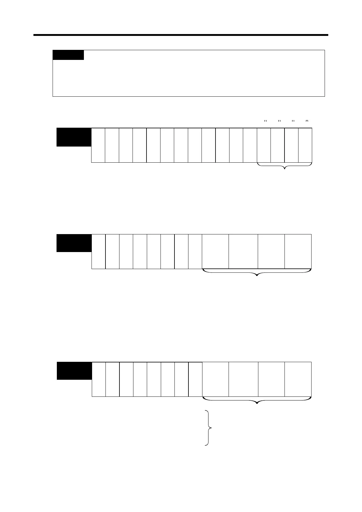
(2) The system area (after No. 22) is prohibited to read/write.
If this area is changed, malfunctions or breakdowns will be happened.
1) Operation channel setting
If the operation channel is not set, all channels will be stopped.
C
h
a
n
n
e
l
3
C
h
a
n
n
e
l
2
C
h
a
n
n
e
l
1
C
h
a
n
n
e
l
0
------
Address
No. 0
Designation of used channel
Bit On (1): In operation
Bit Off (0): Stop
---
- --
Bit 15 Bit 14 Bit 13 Bit 12 Bit 11 Bit 10 Bit 9 Bit 8
Bit 7
Bit 6 Bit 5 Bit 4 Bit 3 Bit 2 Bit 1 Bit 0
2) Output range setting
The range of analog output voltage is DC 0 ~ 10V. And the range of analog output current is DC 4
~ 20mA, DC 0 ~ 20mA.
Output range setting (Channel per 2 bits)
00 : 1 ~ 5V (4 ~ 20 ㎃)
01 : 0 ~ 5V (0 ~ 20 ㎃
10 : 0 ~ 10 V
11 : -10 ~ 10 V
Channel 1
Channel 2
Channel 3
-
---
--
-
-
Bit 15
Bit 14
Bit 13
Bit 12
Bit 11
Bit 10
Bit 9
Bit 8
Bit 7
Bit 6
Bit 5
Bit 4
Bit 3
Bit 2
Bit 1
Bit 0
3) Input data type setting
(1) Input data type can be set for each channel.
(2) All channels will be handled as the range of 0~ 16,000 when the input data type is not set.
Input data type setting (2 bits per channel)
00 : 0 ~ 16000
01 : -8000 ~ 8000
10 : Precise value
11 : 0 ~ 1000
-In case of precise value
4 ~ 20㎃: 4000 ~ 20000
0 ~ 20㎃: 0 ~ 20000
1 ~ 5V: 1000 ~ 5000
0 ~ 5V: 0 ~ 5000
0 ~ 10V: 0 ~ 10000
-10 ~ 10V: -10000 ~ 10000
Channel 1
Channel 2Channel 3
---- ----
Bit 15 Bit 14 Bit 13 Bit 12
Bit 11 Bit 10 Bit 9 Bit 8 Bit 7 Bit 6 Bit 5 Bit 4 Bit 3
Bit 2 Bit 1 Bit 0
14 - 33
 Loading...