Chapter 15 PID Function (Built-in function)
15 - 43
(4) Water Level Sensor
A water level sensor plays a role to deliver the PV of an object to control to XGB by measuring the
water level of a pail and outputting it within 0 ~ 10V. Since the types and output scope of water
level sensors varies, the output scope of a sensor should be identical with that of A/D input
module’s input scope. The example uses a water level sensor outputting between 0 ~ 10V.
(5) Drive (pump)
A drive uses a pump that receives control output of XGF-DV04A and of which rotation velocity is
variable. For accurate PID control, the output scope of XBF-DV04A (0~10V) should be same with
that of a pump’s control input. The example uses a pump that receives its control input between 0 ~
10V.
15.5.2. Example of PID Auto-tuning
Here, with examples, it explains how to calculate proportional constant, integral time and differential
time by using PID auto-tuning function
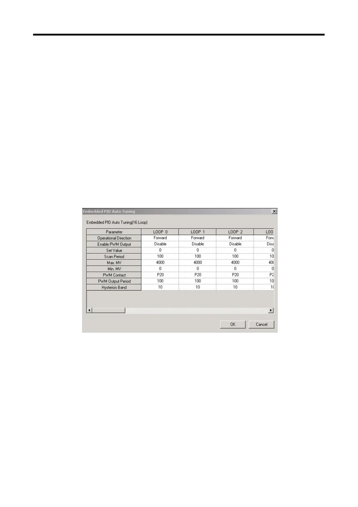
(1) PID auto-tuning parameter setting
(a) If double-clicking Parameter – Built-in Parameter – PID – Auto-tuning parameter in the
project window, it opens up the auto-tuning parameter setting window as illustrated in
Figure 15.18.
[Figure 15.18 Auto-tuning parameter setting window]
(b) Set each parameter and click OK.
In the example, Loop 0 is set as follows.
RUN direction: forward
- Since in the system, water level is going up as MV increases and pump’s rotation
velocity increases, it should be set as forward operation.
PWM output: disabled
- In the example, auto-tuning using PWM is not executed. Therefore, PWM output is set
as disabled.
SV: 1000(2.5V)
- It shows an example in which XBF-AD04A is set as the voltage input of 0~10V.
 Loading...